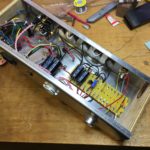
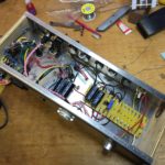
This is a bit of a photo journal of the construction of my guitar amp. This was a very enjoyable process and I am pretty happy with the amp. Credit for the amplifier design goes to the fabulous site http://www.ax84.com/.
My amp is a minor variation on the P1 Extreme circuit from the chaps at ax84.
The cabinet design is my own, but some credit needed for the inspiration given by Uncle Doug
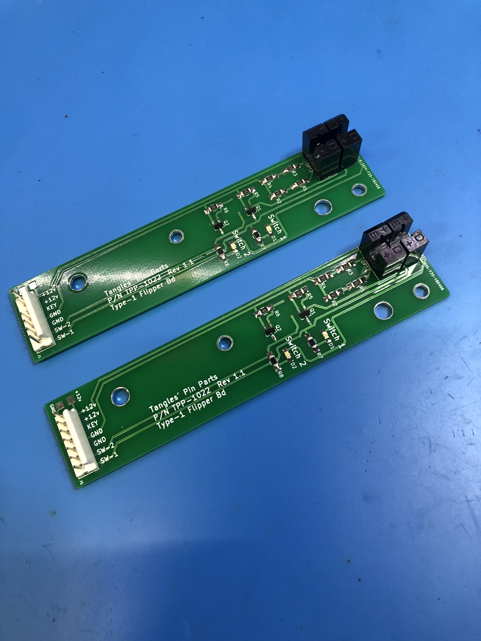
Working on a Bally World Cup Soccer. This machine is resetting often. This has got progressively worse. The machine powers on, but every time the flipper buttons are pressed, the machine resets.
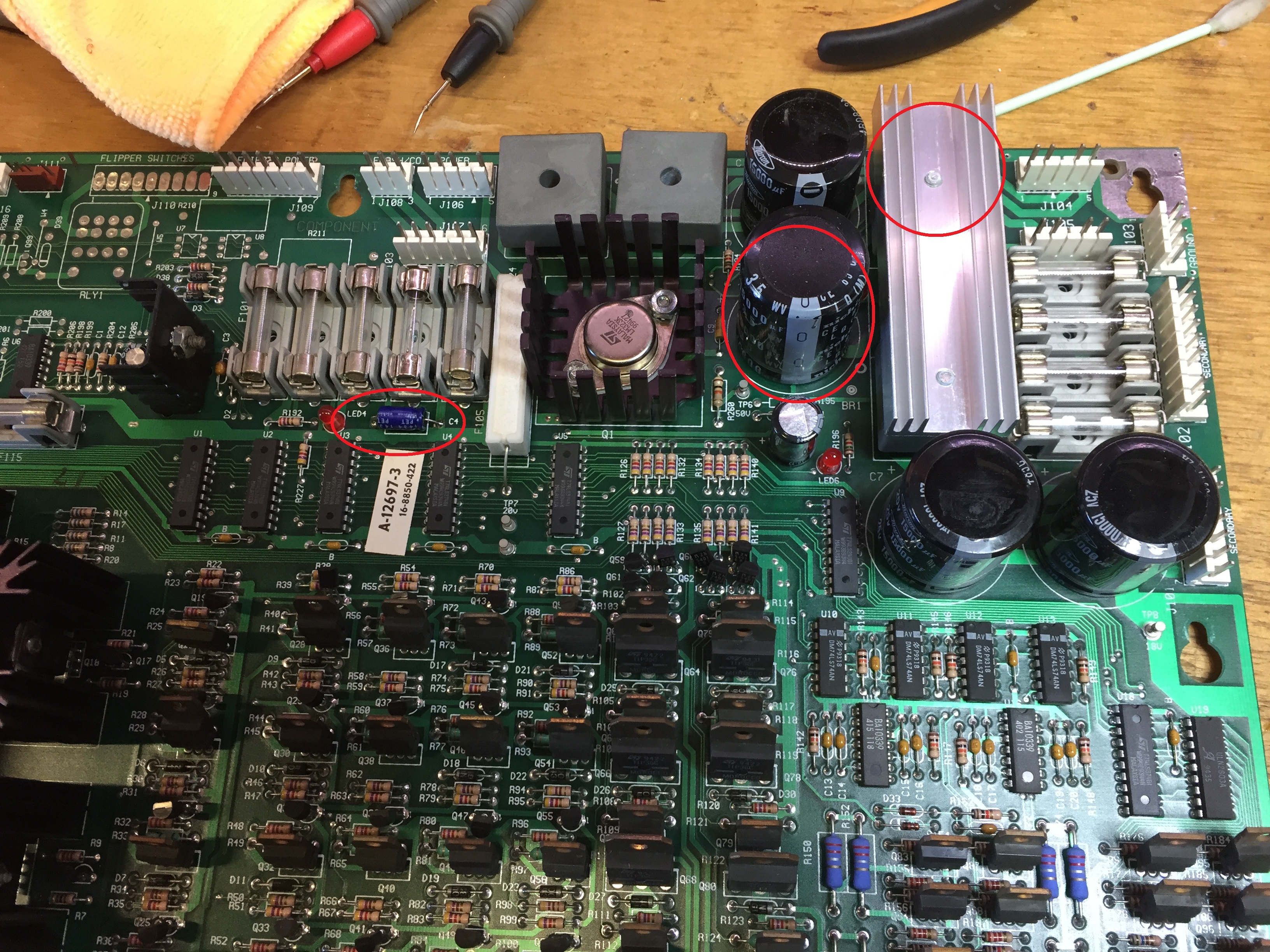
Using a Digital multi-meter, I confirmed the 5v was good at 5.05. However, when I switched to AC, the reading was showing more than 0.5V ripple. The power driver board was returned to my shop for an overhaul.
This board was in very good condition. I note that the 5V rectifier and capacitor had already been changed, but with the “plastic” 3504 style rectifier. I replaced this with a 3506 (full metal shell).
Put a new capacitor in C5 (15,000 uF), BR2 and C4. I have found C4 to be often neglected in boards I have come across.
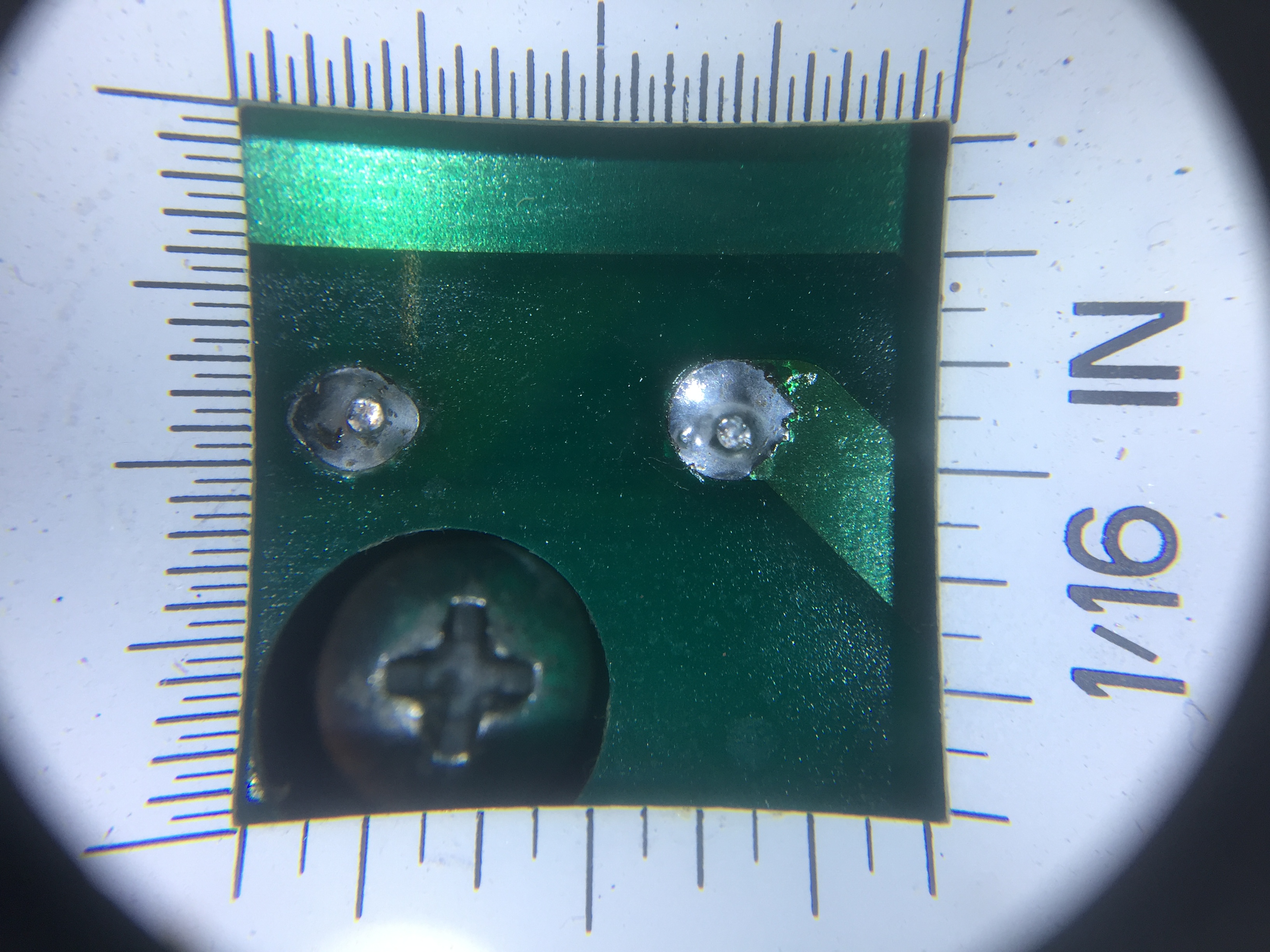
As usual, I took the time to clean the board and inspect the solder joints. There should be no reason we can’t leave the board with solder as good (or better) than the factory.
This picture show using a illuminated loupe to inspect the soldering (repair) on the rectifier.
Board was returned to the game and is now working fine!
Except…. on the first play test, the Goalie (plastic) broke in two….
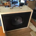
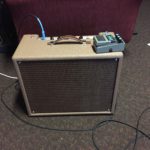
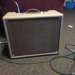
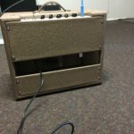
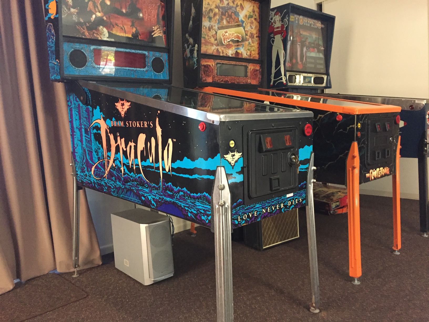
Hacking a faulty “Panasonic DVD Home Theatre Sound System” player to function as a powered sub woofer for my “Bram Stroker’s Dracula” pinball machine.
The objective of this hack was to modify the powered sub woofer to enable a speaker level input (from the pinball), a volume control and an automatic power switch.
Having come across a faulty home theatre system I found that it had multiple faults. The circuitry however on the powered woofer enclusure was looking to be in good order and importantly – all analogue!
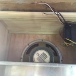
The enclosure houses a sub woofer speaker, power supply and an integrated amplifier for all 5 channels. I set to tracing out the connection so that I might hack into the unit and make use of the sub woofer channel to server as a powered driver for my BSD pinball.
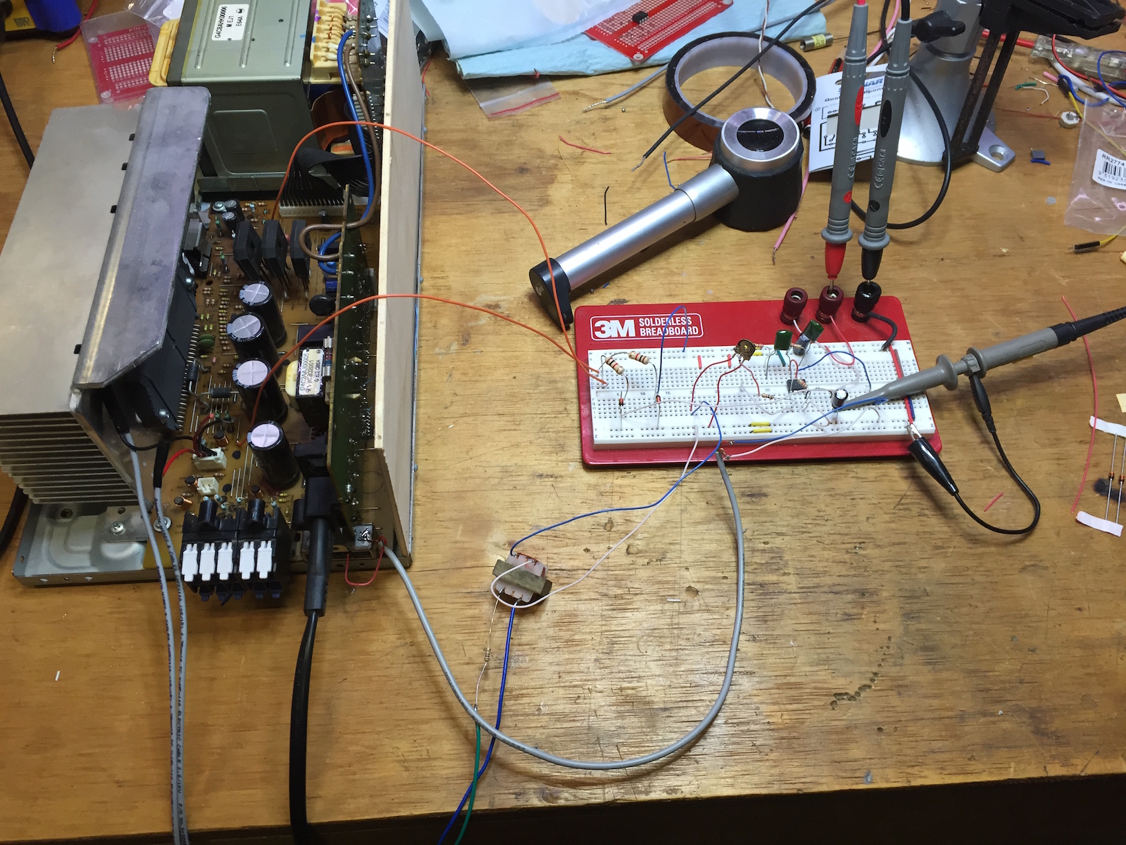
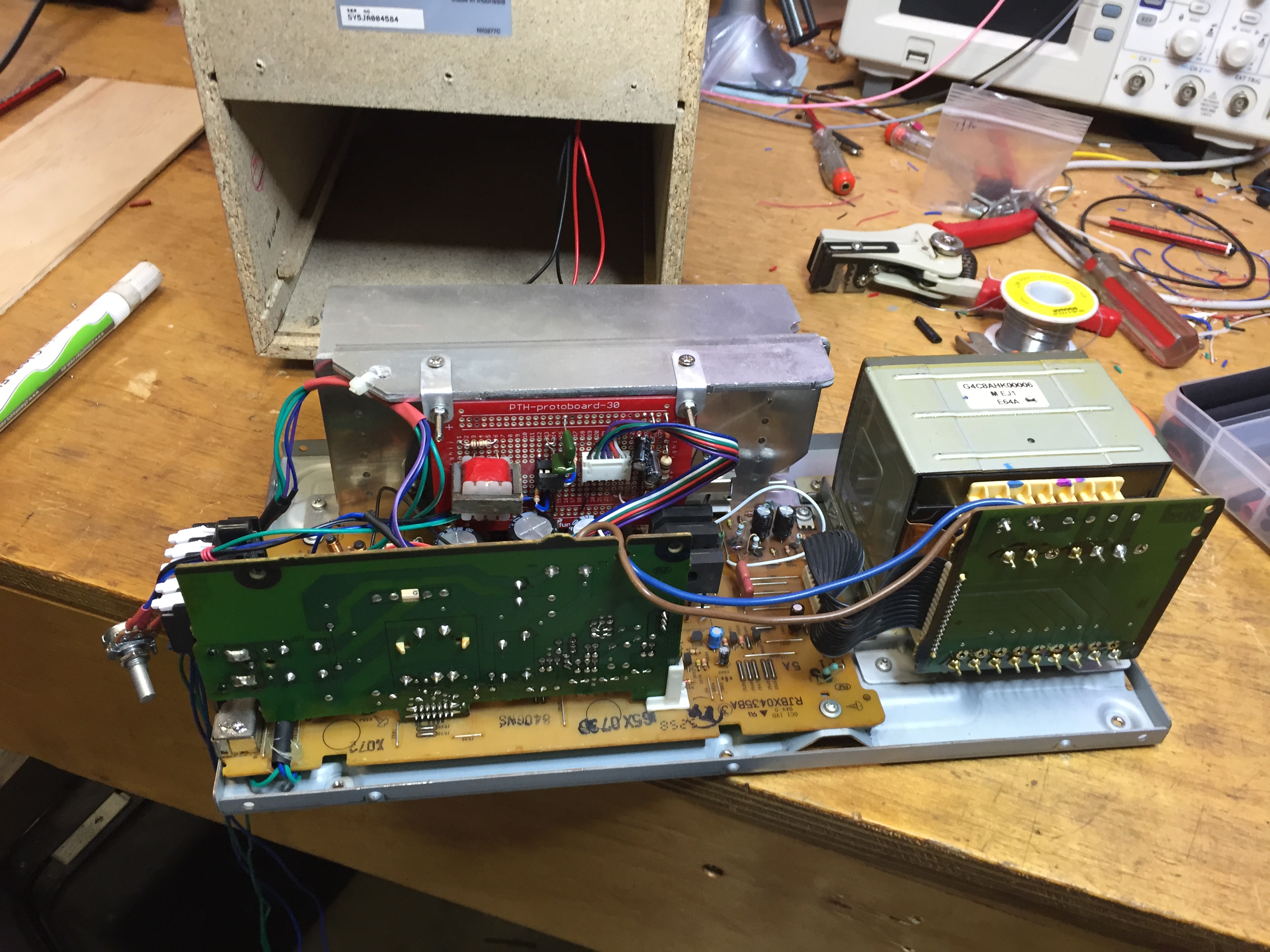
Finished and installedPrototypeMod board installed
Working with the powered speaker was particularly dangerous due to the “live” AC inlet PCB. This PCB provides the standby 6v power supply and a relay to switch the main transformer on and off. I recommend this type of work be left to people with a lot of experience in servicing live electronics.
Circuit
I found a PDF online with the full schematic for the active speaker. This was invaluable for the project. The document covered the subwoofer / amplifier unit only. Whilst I was certain the DVD player originally attached to the unit was faulty, I also found that two of the bridge rectifiers in the active sub woofer had cracked joints. These needed re-flowing.
Power Switch
The power switch was achieved by tapping into the SB-WA840EE power on relay circuit. The standby 6v supply can be used to trigger the mains relay. Connecting CN502 pin 2 to (PCONT) to pin 5 (6v) will power the unit up.
A relay was installed in the pinball to complete this circuit when the pinball was powered on. Using a piece of vero board and a small relay, I used a 12v supply from the coin door interface board to activate the relay. The N/O contacts were wired to the 4 wire plug hanging out of the cabinet bottom.
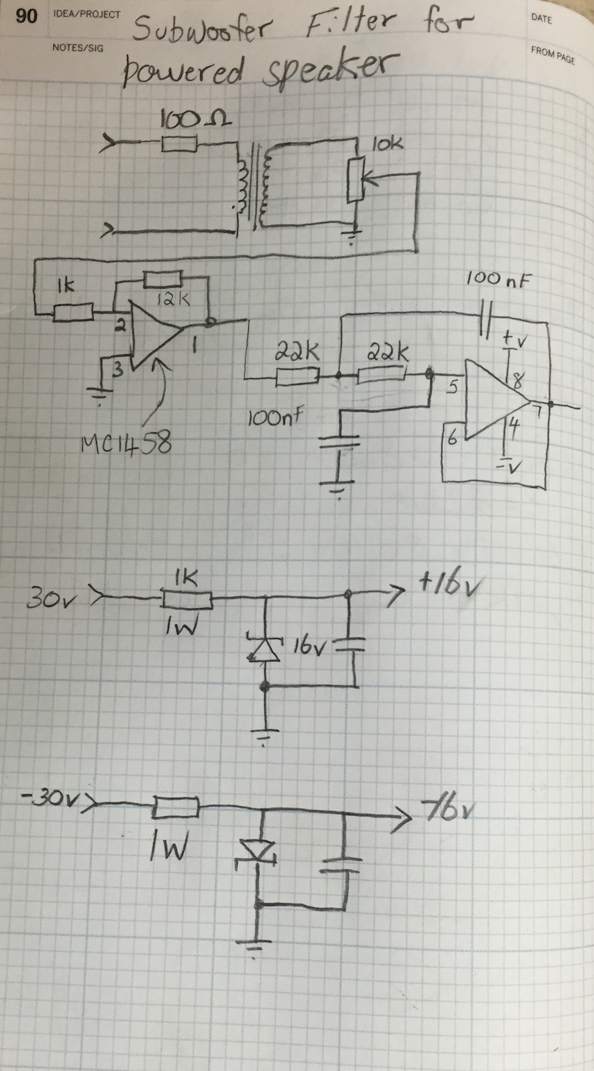
Low Pass Filter
Low pass filter circuit
The filter circuit employed is a 2nd order active low pass filter. I found this resource from TI to be very useful in the design of this circuit.
Note that the first opamp in the circuit is configured as a 12x inverting buffer. This takes the low level input signal from the isolation transformer and amplifies it to approximately 100mv P-P (with a low to moderate input speaker volume).
The 10K potentiometer provides an adjustment of the level accessible from the back of the speaker enclosure.
Balanced Input
I used a salvaged audio transformer to decouple the incoming audio from the active speaker. Using this means the polarity of the speaker connection is not important. It also keeps the pinball fully isolated from the speaker. I felt this was important as the sub woofer was a double insulated device (no earth) and the pinball utilises a fully earthed design. I thought this prudent for safety as well as for minimising mains hum.
Op Amp Power Supply
I was able to tap the +/- 30v supply from the main amplifier. Feeding to two 1K 1W resistors and 16v zener diodes gave me a suitable +/- 16v supply for the filter. I used an online calculator [here] to size the resistors. I allowed for 5 mA of current for this simple regulated supply.
Pinball Tap
The pinball tap was a 4 wire connection. The two speaker wires from the cabinet speaker, and two wires from the relay contacts make up the 4 wire plug. I user a 4 circuit Molex plug to enable the powered speaker to be disconnected as required.