The
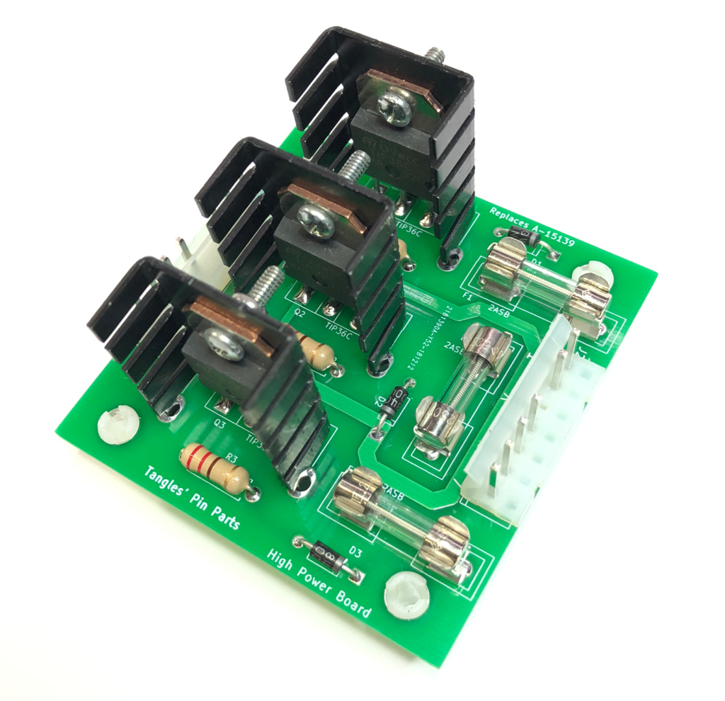
TPP-1030 board is redesigned replacement for the original A-15139 High power
driver. Whilst this board is generically
known as a high power driver board, it was used only on The Addams Family
machines to drive the three playfield magnets.
The
original board has been known to fail locking one or more magnets on. This can
lead to a burnt / scorched playfield… ouch!
Whilst
there is a 5 AMP fuse in-line with the original board, this fuse is across all
three magnets and typically does not blow when there is a single failed driver
transistor and one of the magnets is permanently activated.
The
recommended fix for this situation is to add individual (smaller valued) fuses
to the 3 magnet circuits. This can now be done neatly and easily with this
redesigned board featuring 3 on-board fuses.
Installation
is a snap, fits original mounting holes and original Molex connectors.
Replacement should take only a few minutes.
This board ships with 4 nylon mounts, 3 x 2A fuses installed and 2 spare fuses.
INSTALLATION
Warning: High voltages are present inside the pinball machine. Ensure the power is off and the mains cable is disconnected before you commence work.
Ensure power is off to the machine.
Remove the playfield glass and raise the playfield.
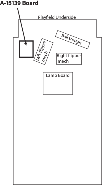
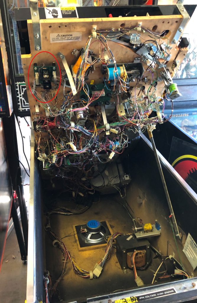
Locate the existing A-15139 board adjacent the left flipper mechanism
Remove two connectors (7-way and 8way)
Remove original board.
Install TPP-1030 board using original screws.
Reconnect two connectors
FUSE REPLACEMENT
The TPP-1030 uses three 5 x 20mm 2A slow blow fuses. A suitable replacement part is the Littelfuse part no: 0213002.MXP
BOARD LOCATION
Photo – under playfield showing location of A-15139 board
Replacement for A-18543-1, A-18543-2, A-18543.1-2 and A-16922
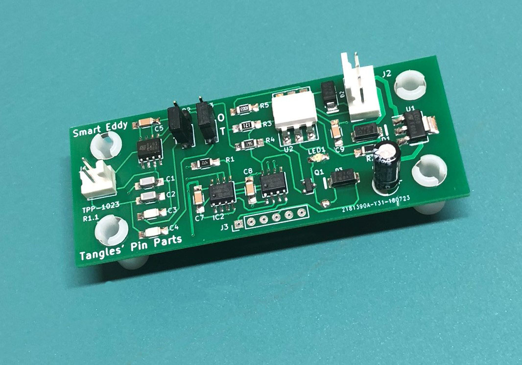
Smart Eddy (TPP-1023) is a re-designed “Eddy” proximity detector compatible with the games “Theatre of Magic”, “Star Trek – The Next Generation”, “Scared Stiff” and “Road Show”. The Smart Eddy board has an auto calibration feature that automatically adjusts the detector circuit each time the machine is turned on. This amazing auto calibration feature will free operators and owners from the tyranny of sensor adjustments that plague these games. Aging boards, playfield vibration and shaker motors all conspire to making the original boards a troublesome item.
The TPP-1023 board is a drop in replacement and amazing upgrade to the original boards. Matching the electrical and screw mounting* characteristics of the original parts, this re-designed unit can be installed easily with little fuss.
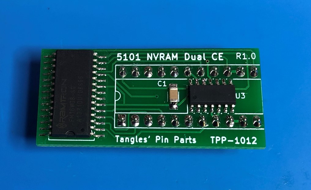
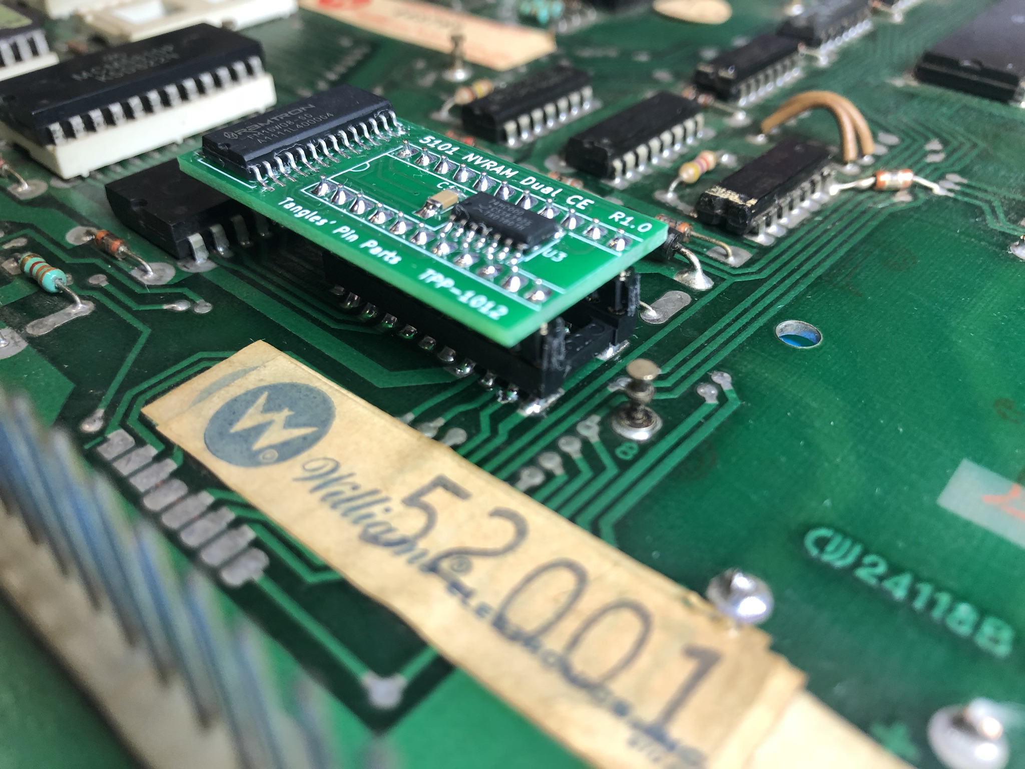
This blog details the installation of a 5101 NVRAM into a Williams System 6 machine. The part used here is from Tangles’ Pin Parts – p/n TPP-1012.
If you want to purchase one of these NVRAMs then click here…
The procedure is ranked as difficulty high because the 5101 memory needs to be de-soldered from the board and a socket installed.
This procedure is very similar for System 3 to System 7 systems.
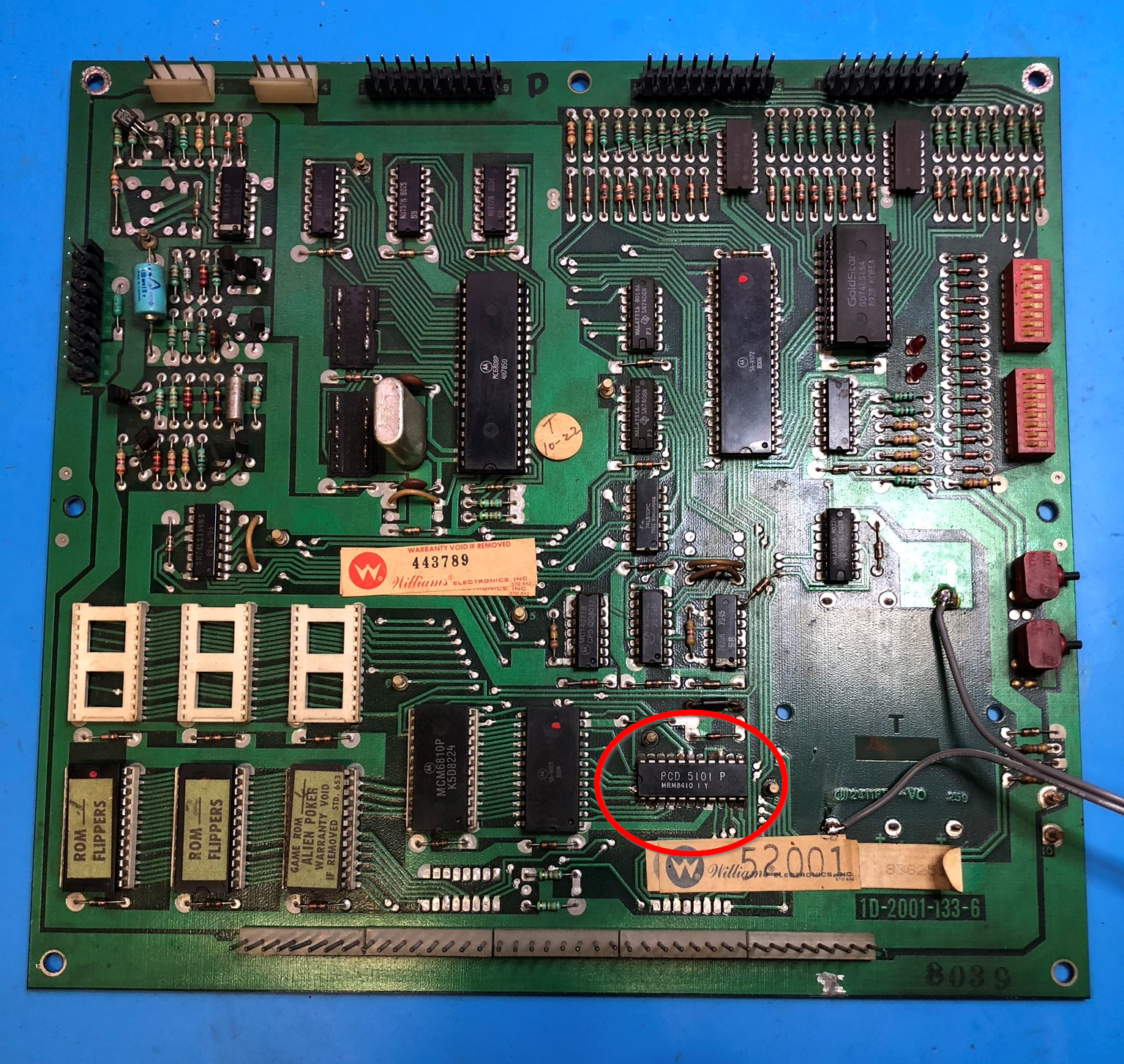
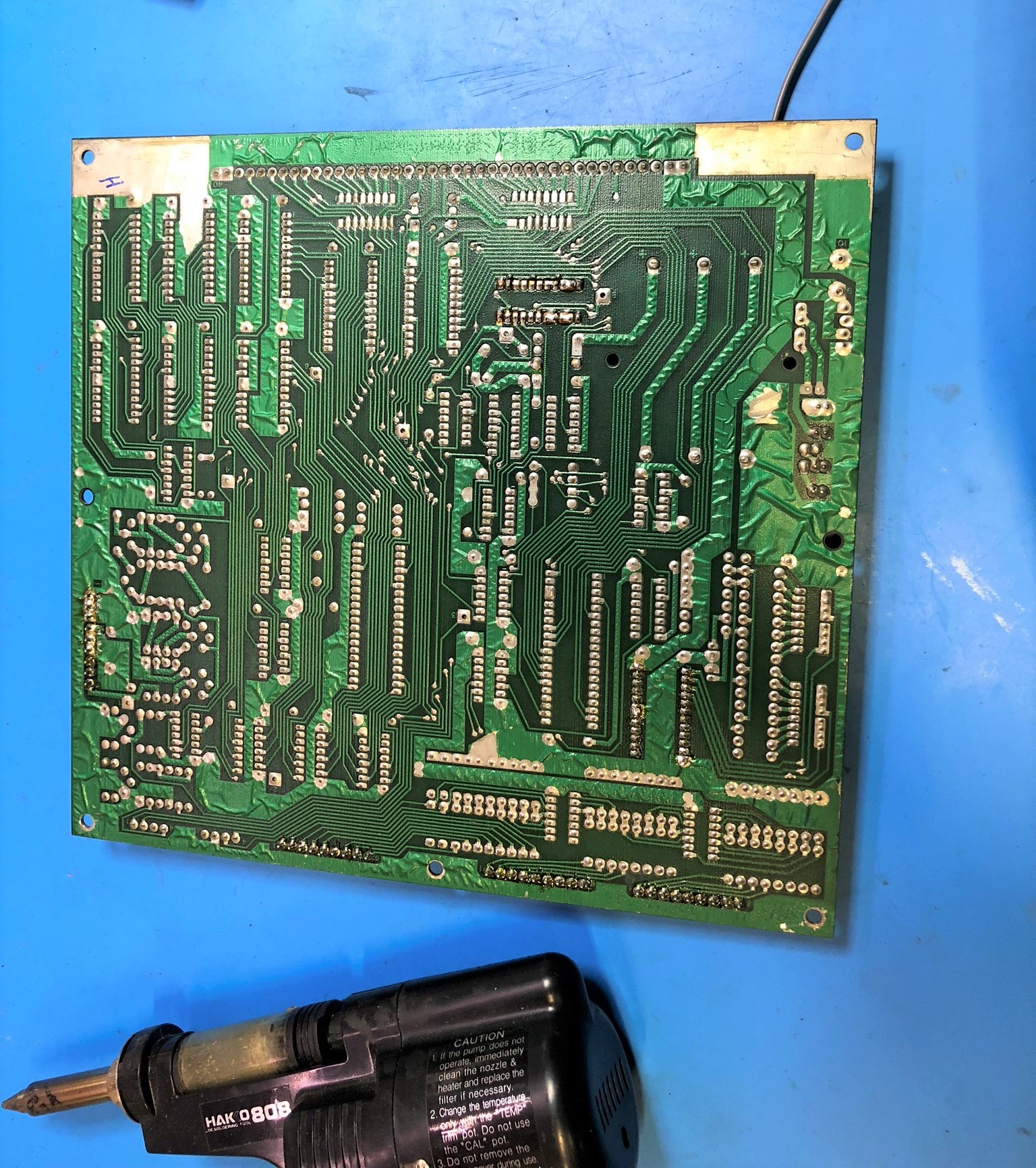
Having removed the CPU boards from the pinball machine, we start by removing the batteries. On the board pictured below, the batteries are removed from the attached remote battery holder.
Identify the 5101 chip on the CPU board.
The Williams boards have fat traces so de-soldering is easier and safer than on some other systems.
Flip the board over and de-solder the 5101 chip.
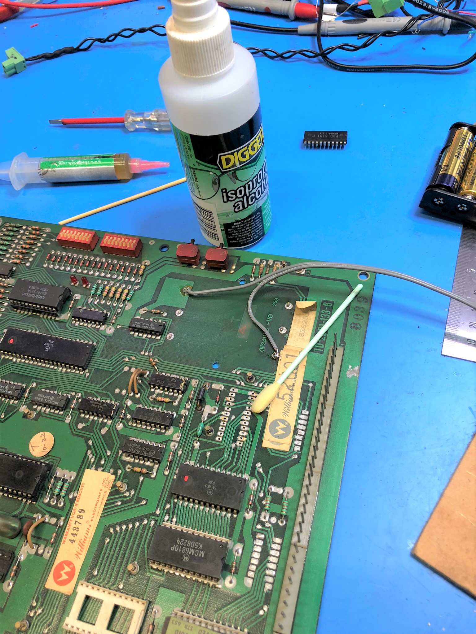
I used isopropyl alcohol to clean the top and bottom of the board in readiness for the new socket.
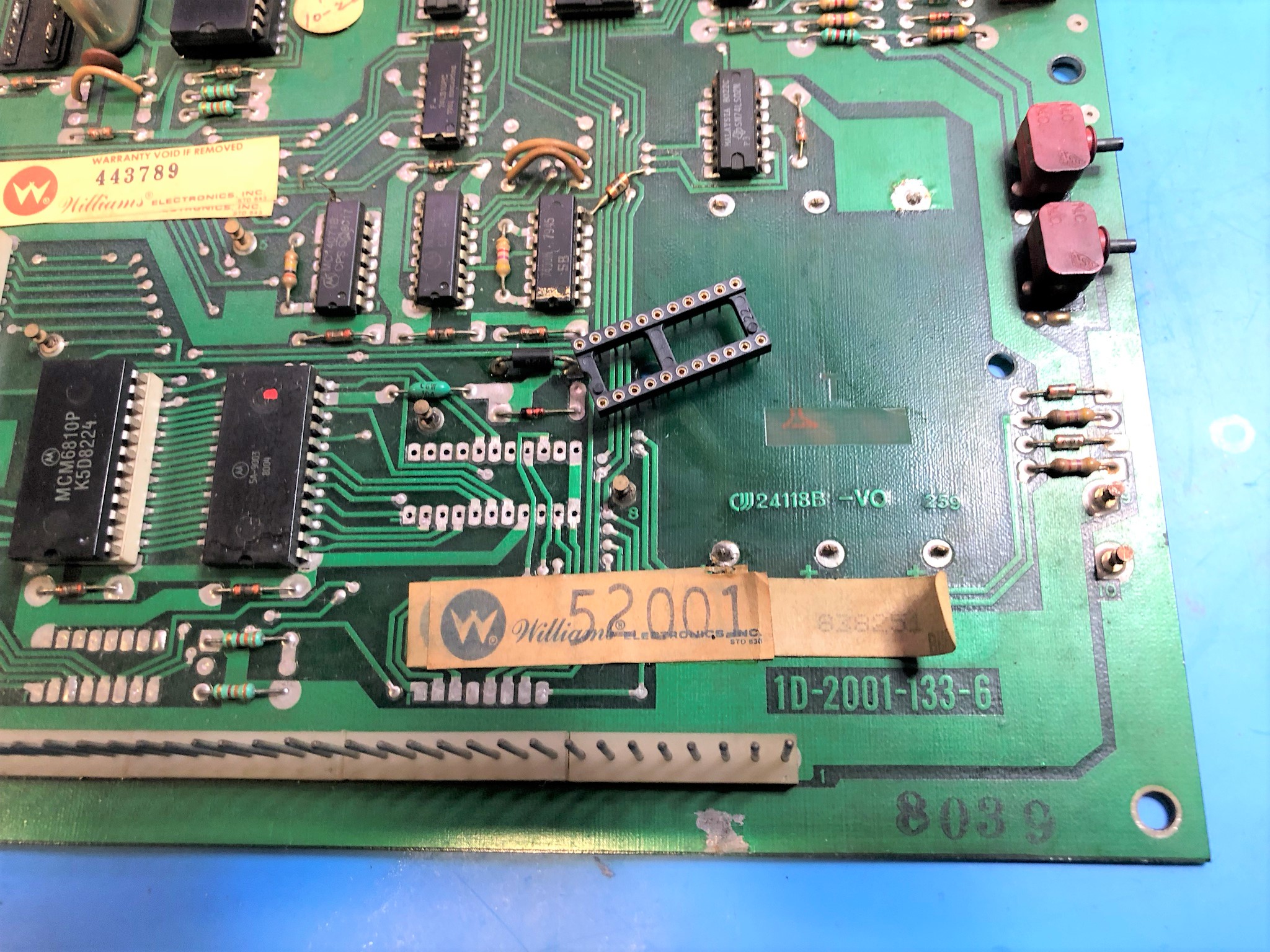
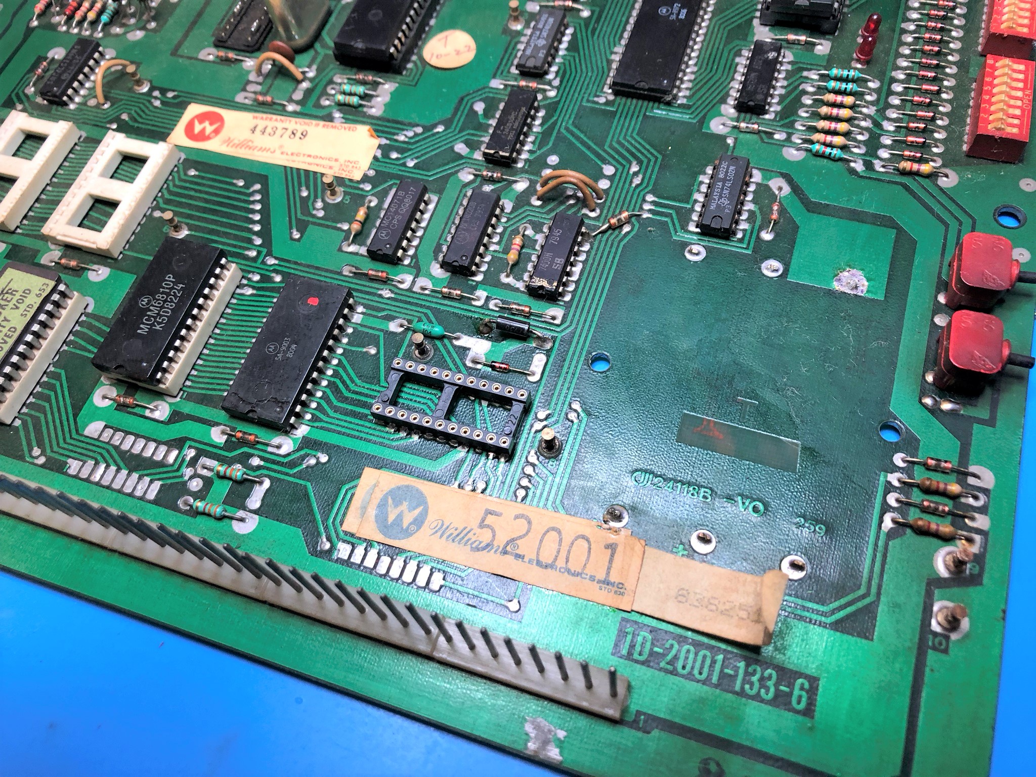
The 22 pin IC socket is now ready for installation
The socket is installed. Give the new solder joint a clean with IPA.
Using a turned pin socket is recommended as it lets you inspect the solder joint from the top and the bottom. Make sure the new socket has good solder flow on both the top and the bottom. It is very important on these old boards to not rely on the thru-plating to connect the top and bottom of the board.
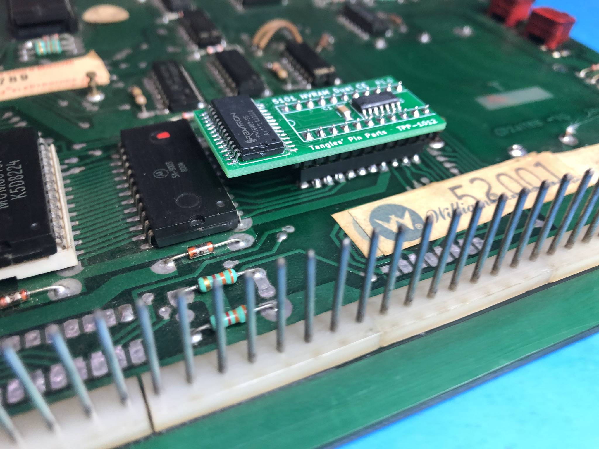
Now it’s time to install the NVRAM module. Take care to install in the right way round and ensure all 22 pins mate with the IC socket.
The CPU board has had a final inspection and is ready to re-install in the pinball machine.
All audits and saved data will be lost. When re-powering the System 6 it will enter the audit mode, showing ROM version number in the top left display. To clear this mode you need to open the coin door and flick the power off and on quickly.
I recommend using the machine manual and go through all system settings and set them to your requirements… (eg free play and number of balls).
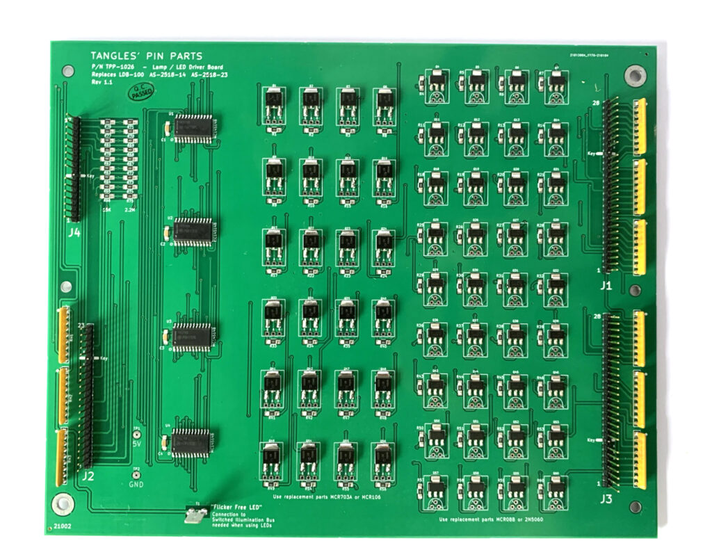
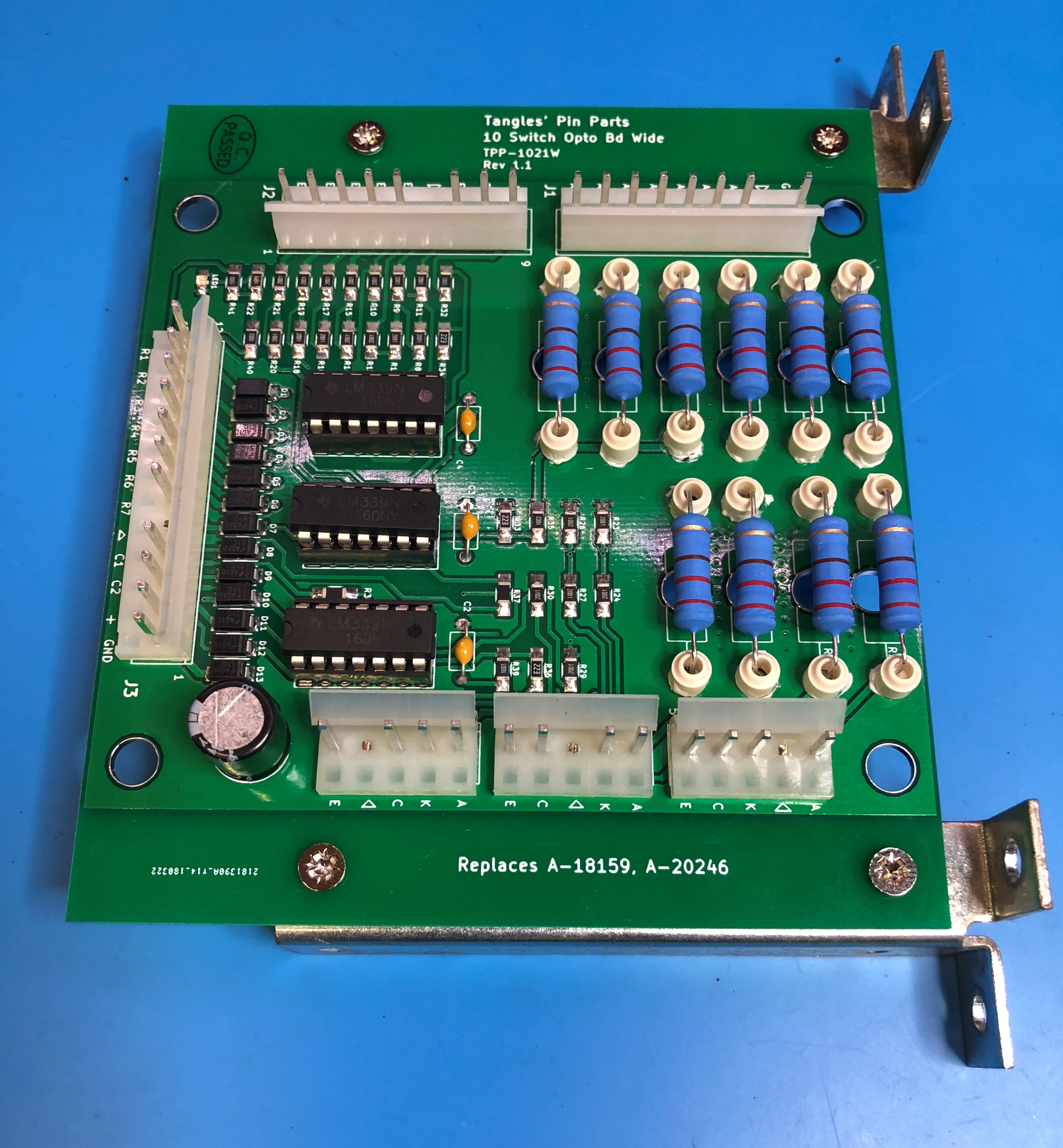
Tangles presents here a replacement for the Bally/Williams 10-opto board. Time has not been kind to these boards. The original boards typically fail from over temperature; the heat being generated by the 10 large resistors on the board.
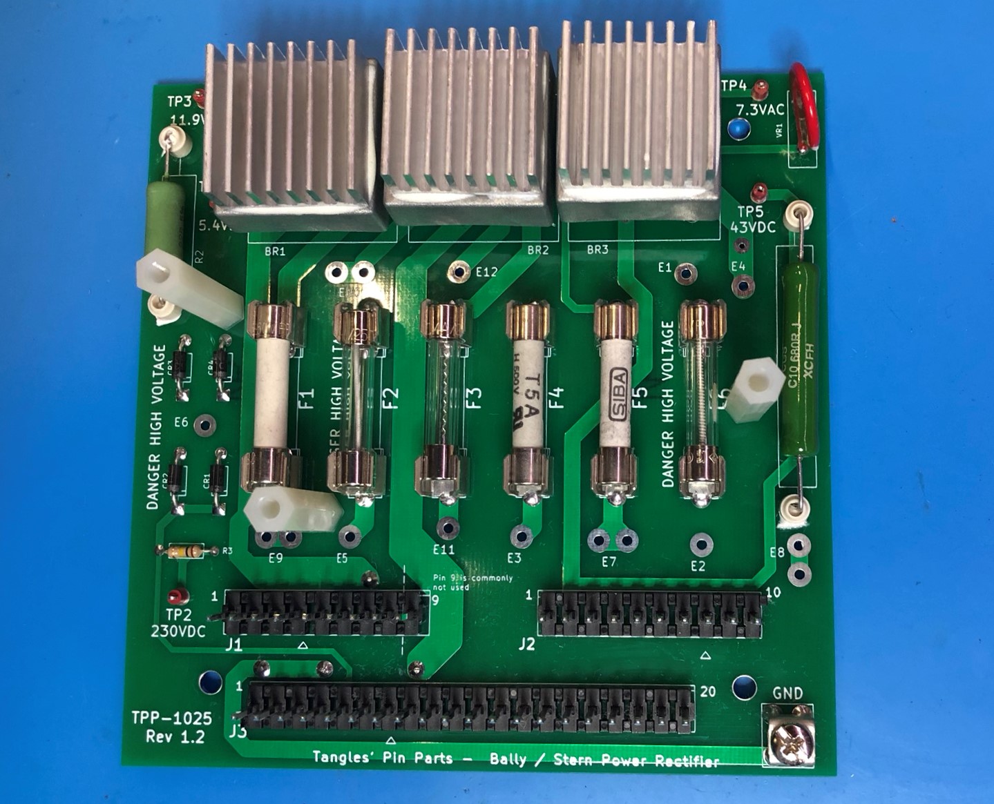
Tangles presents a board to replace Stern TA100 and Bally AS-2518-18 rectifier boards. The original boards suffer from undersized rectifiers, over-heating and high current stress in the through-hole plating of some connectors.
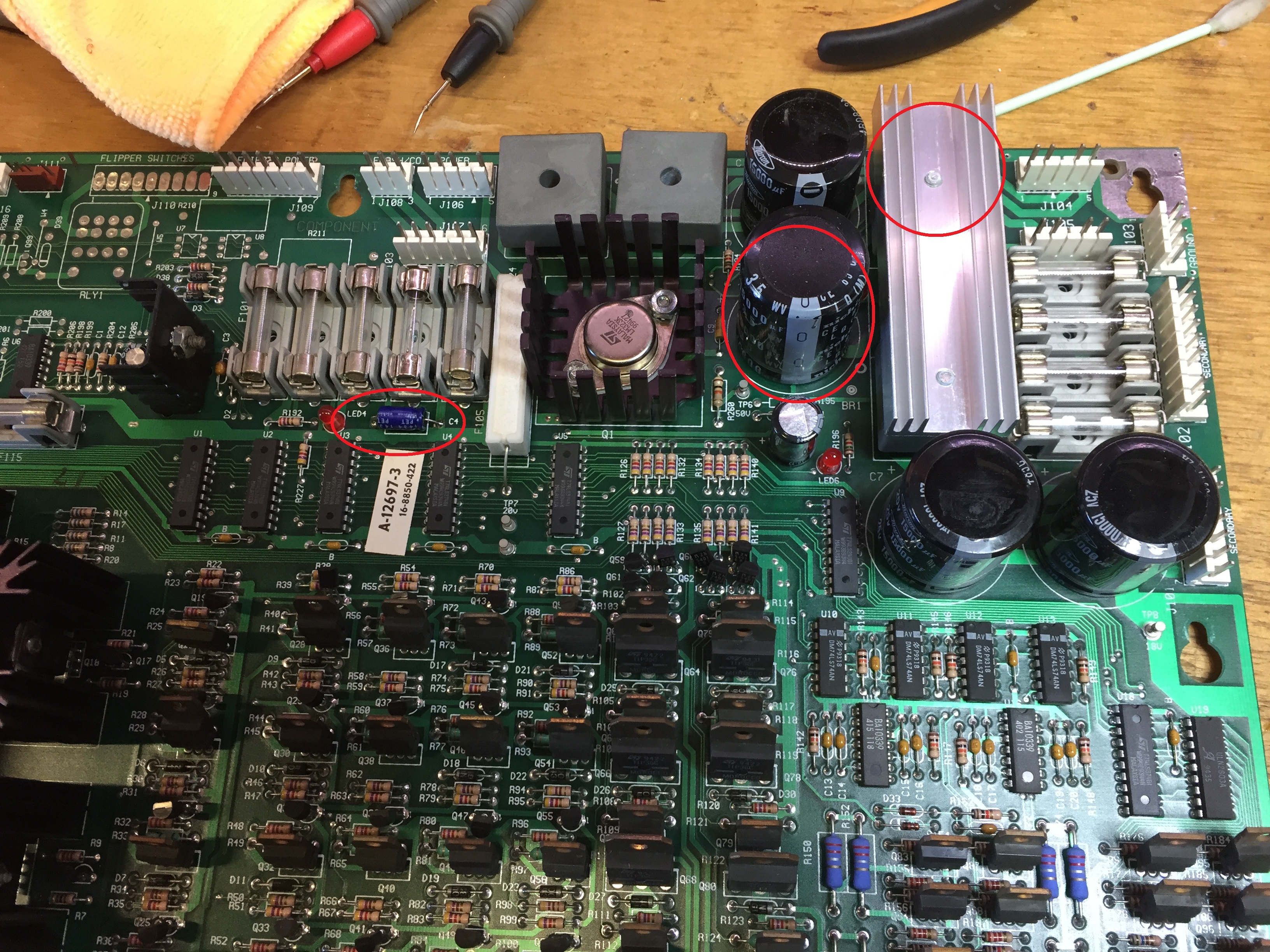
Working on a Bally World Cup Soccer. This machine is resetting often. This has got progressively worse. The machine powers on, but every time the flipper buttons are pressed, the machine resets.
Using a Digital multi-meter, I confirmed the 5v was good at 5.05. However, when I switched to AC, the reading was showing more than 0.5V ripple. The power driver board was returned to my shop for an overhaul.
This board was in very good condition. I note that the 5V rectifier and capacitor had already been changed, but with the “plastic” 3504 style rectifier. I replaced this with a 3506 (full metal shell).
Put a new capacitor in C5 (15,000 uF), BR2 and C4. I have found C4 to be often neglected in boards I have come across.
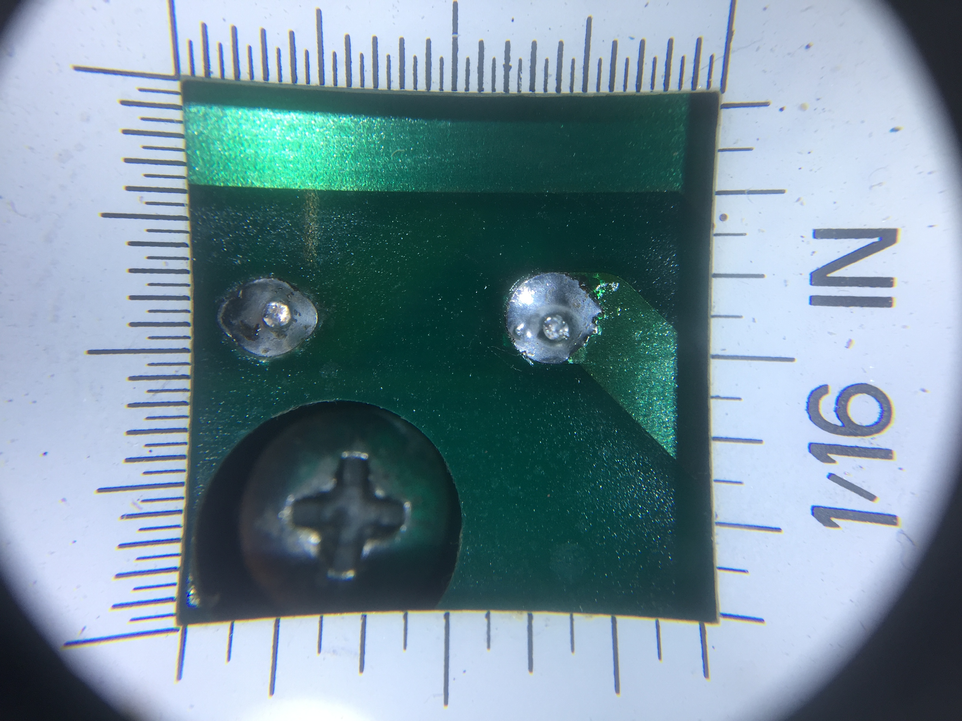
As usual, I took the time to clean the board and inspect the solder joints. There should be no reason we can’t leave the board with solder as good (or better) than the factory.
This picture show using a illuminated loupe to inspect the soldering (repair) on the rectifier.
Board was returned to the game and is now working fine!
Except…. on the first play test, the Goalie (plastic) broke in two….
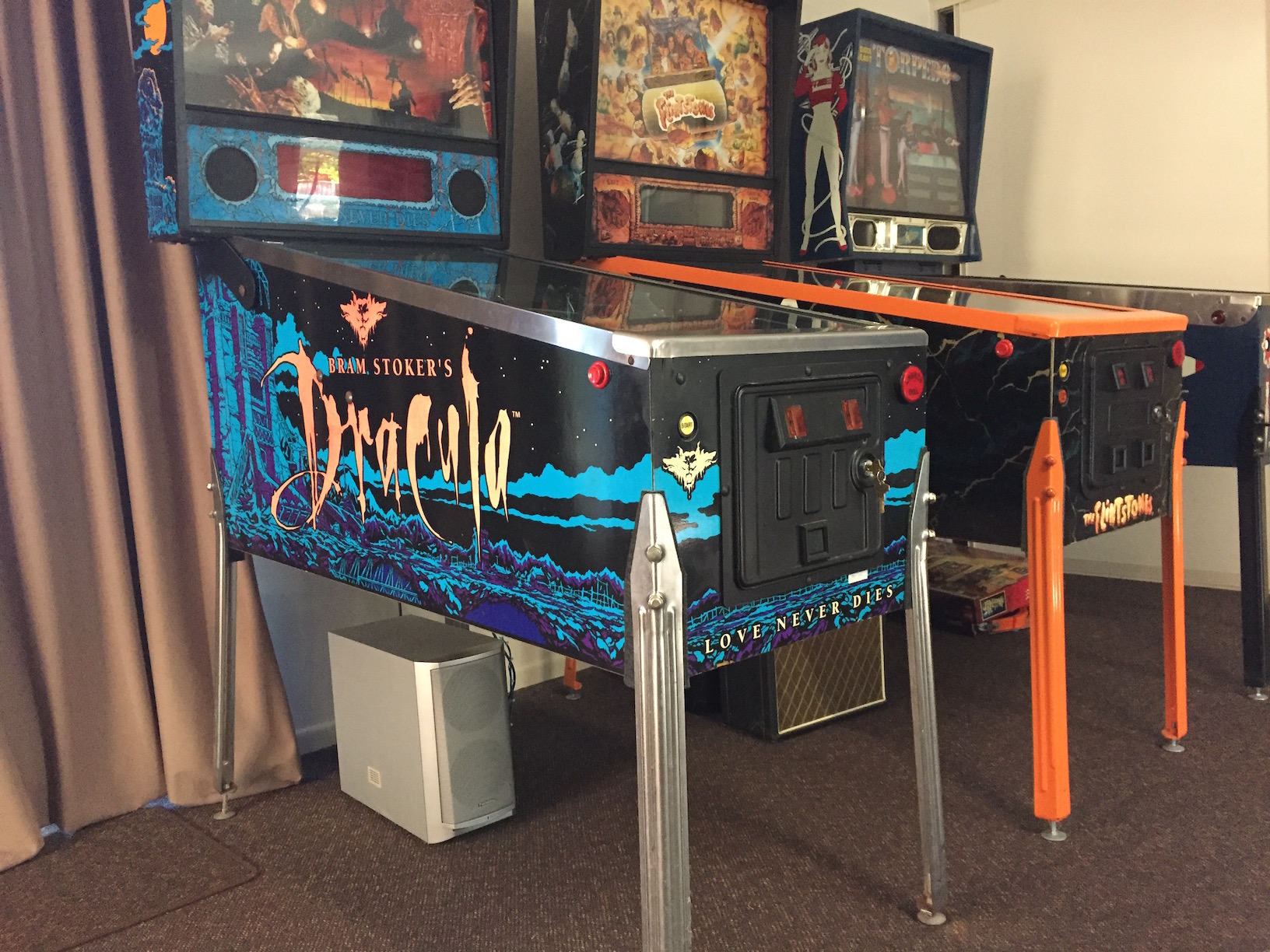
Hacking a faulty “Panasonic DVD Home Theatre Sound System” player to function as a powered sub woofer for my “Bram Stroker’s Dracula” pinball machine.
The objective of this hack was to modify the powered sub woofer to enable a speaker level input (from the pinball), a volume control and an automatic power switch.
Having come across a faulty home theatre system I found that it had multiple faults. The circuitry however on the powered woofer enclusure was looking to be in good order and importantly – all analogue!
The enclosure houses a sub woofer speaker, power supply and an integrated amplifier for all 5 channels. I set to tracing out the connection so that I might hack into the unit and make use of the sub woofer channel to server as a powered driver for my BSD pinball.
Finished and installed
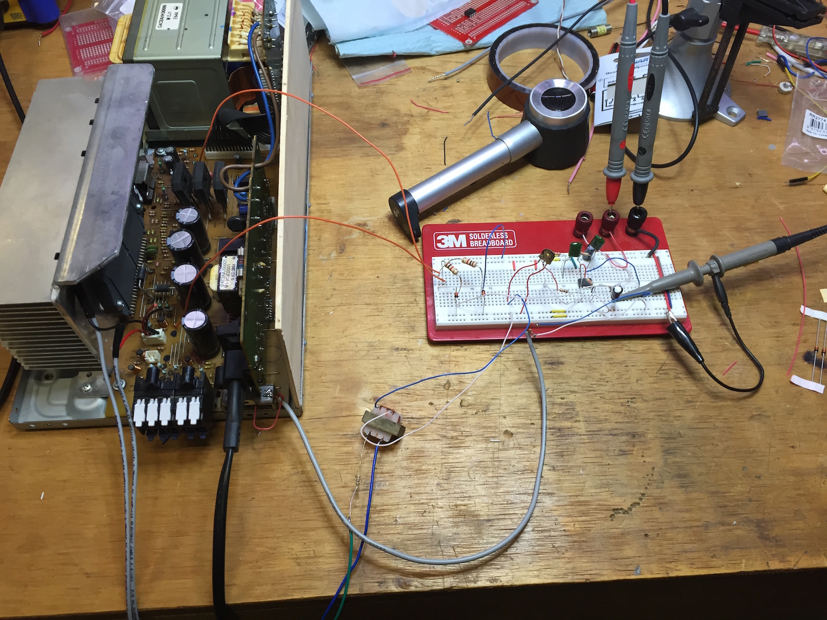
Prototype
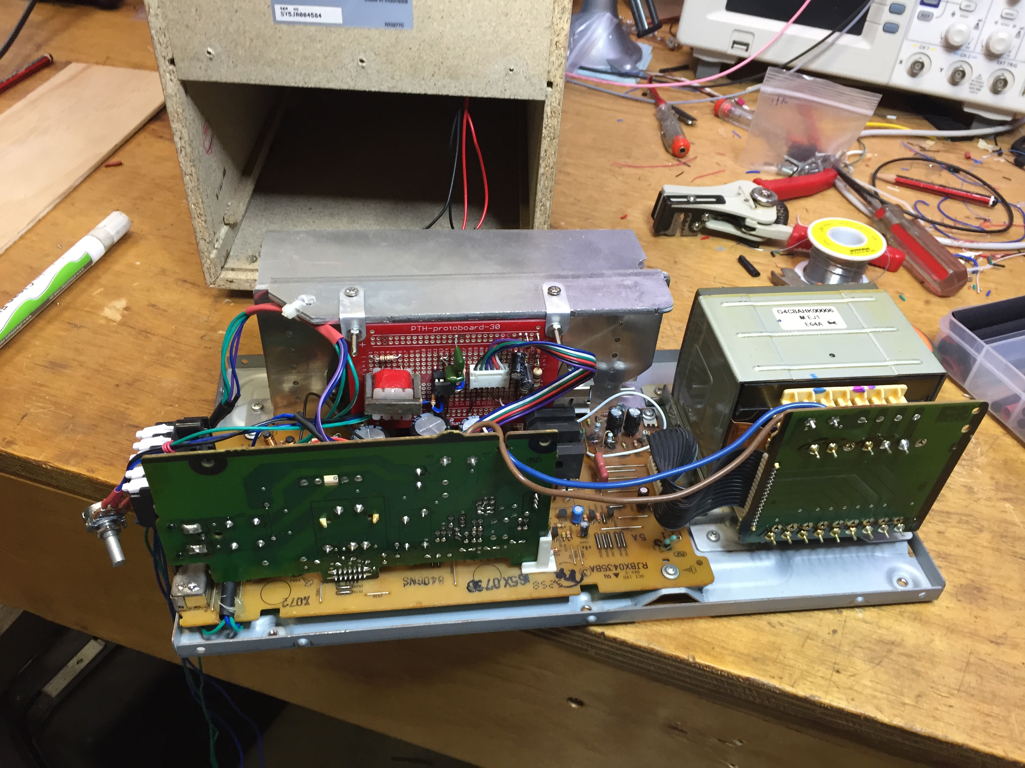
Mod board installed
Working with the powered speaker was particularly dangerous due to the “live” AC inlet PCB. This PCB provides the standby 6v power supply and a relay to switch the main transformer on and off. I recommend this type of work be left to people with a lot of experience in servicing live electronics.
Circuit
I found a PDF online with the full schematic for the active speaker. This was invaluable for the project. The document covered the subwoofer / amplifier unit only. Whilst I was certain the DVD player originally attached to the unit was faulty, I also found that two of the bridge rectifiers in the active sub woofer had cracked joints. These needed re-flowing.
Power Switch
The power switch was achieved by tapping into the SB-WA840EE power on relay circuit. The standby 6v supply can be used to trigger the mains relay. Connecting CN502 pin 2 to (PCONT) to pin 5 (6v) will power the unit up.
A relay was installed in the pinball to complete this circuit when the pinball was powered on. Using a piece of vero board and a small relay, I used a 12v supply from the coin door interface board to activate the relay. The N/O contacts were wired to the 4 wire plug hanging out of the cabinet bottom.
Low Pass Filter
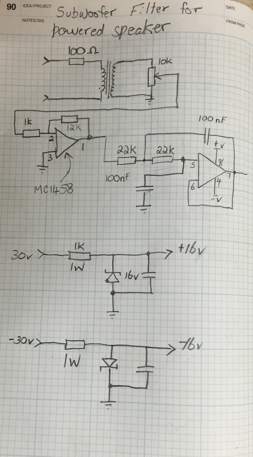
Low pass filter circuit
The filter circuit employed is a 2nd order active low pass filter. I found this resource from TI to be very useful in the design of this circuit.
Note that the first opamp in the circuit is configured as a 12x inverting buffer. This takes the low level input signal from the isolation transformer and amplifies it to approximately 100mv P-P (with a low to moderate input speaker volume).
The 10K potentiometer provides an adjustment of the level accessible from the back of the speaker enclosure.
Balanced Input
I used a salvaged audio transformer to decouple the incoming audio from the active speaker. Using this means the polarity of the speaker connection is not important. It also keeps the pinball fully isolated from the speaker. I felt this was important as the sub woofer was a double insulated device (no earth) and the pinball utilises a fully earthed design. I thought this prudent for safety as well as for minimising mains hum.
Op Amp Power Supply
I was able to tap the +/- 30v supply from the main amplifier. Feeding to two 1K 1W resistors and 16v zener diodes gave me a suitable +/- 16v supply for the filter. I used an online calculator [here] to size the resistors. I allowed for 5 mA of current for this simple regulated supply.
Pinball Tap
The pinball tap was a 4 wire connection. The two speaker wires from the cabinet speaker, and two wires from the relay contacts make up the 4 wire plug. I user a 4 circuit Molex plug to enable the powered speaker to be disconnected as required.