A friend called with a problem on his Data East Hook. When he powers the machine on, it keeps blowing F5 on the PPB board. This fuse is in the AC side of the +50v power rail. Page 46 of the service manual was very helpful, showing that there are only a five high power solenoids on the +50v supply as well as the solid state flippers. My friend unplugged the flipper board and J7 of the PPB and noted the fuse did not blow. Plugging J7 back in blew another fuse. This at least showed us that the problem was not a bad rectifier or capacitor on the PPB nor was the problem in the flipper board.
I immediately suspected a blown (short circuit) driver transistor on the PPB, causing one of the 5 coils to be stuck on. I drove to his house and proceeded to measure the continuity of the big power transistors on the PPB. These are TIP36C. Whilst I have never had one of these fail on me in the past, a faulty or missing coil diode could certainly have caused one of these to fail. Alas, not so. All 5 transistors were testing good using the diode tester on my multimeter.
Ok, time to put some power onto the board and measure which coil is causing the fault. But how to do this without blowing fuses. I used an old trick of replacing the F5 fuse with a resistor. I chose a 5 watt 30 ohm resistor. Hooked up with alligator clips, this resistor would ensure that no more than a couple amps could flow in the 50v circuit even if there was a dead short.
I powered the machine on and noted two things, I could hear a coil buzzing for a couple of seconds and the CPU board was not booting.
A few more power cycles showed the Big-Kick coil was being activated for about 3 seconds when the power came on. It then stopped. This was surely the reason the F5 fuse was blowing. The coils on pinball machines are designed to operated for mere fractions of a second. Holding a high power coil on (with only a few ohms resistance) is more than the 5 Amp fuse can bear. The reason these circuits use slow blow fuses is that the instantaneous kick current pulled by the high power coils is greater than the fuse rating. But performed for such short durations, the fuse is safe. This machine however was holding the coil on for a good few seconds. Plenty of time for the slow blow fuse to circum to the pressure.
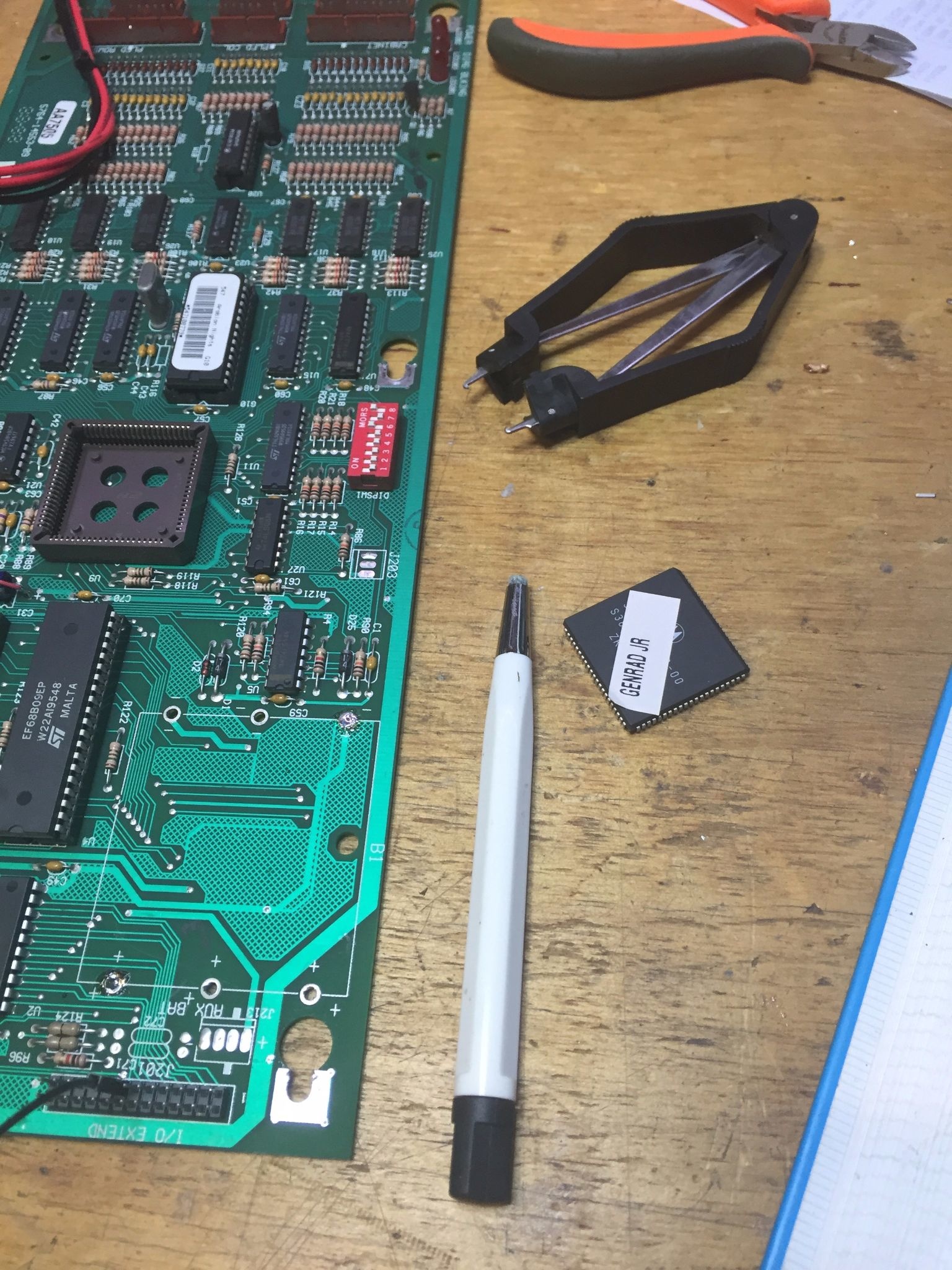
My attention now moved to the other fault on the machine. Not booting. The CPU board LEDS showed 5v and PIA illuminated. The blanking light was out. This means the CPU was not booting! Using my multimeter, I measured the 5 volt sully on the CPU board and got a very unhealthy 4.05 volts. No surprise the CPU board was not running. We were well under the typical minimum good voltage of 4.8v. ( I usually try hard to keep 5 volt rails a touch above 5 volts ).
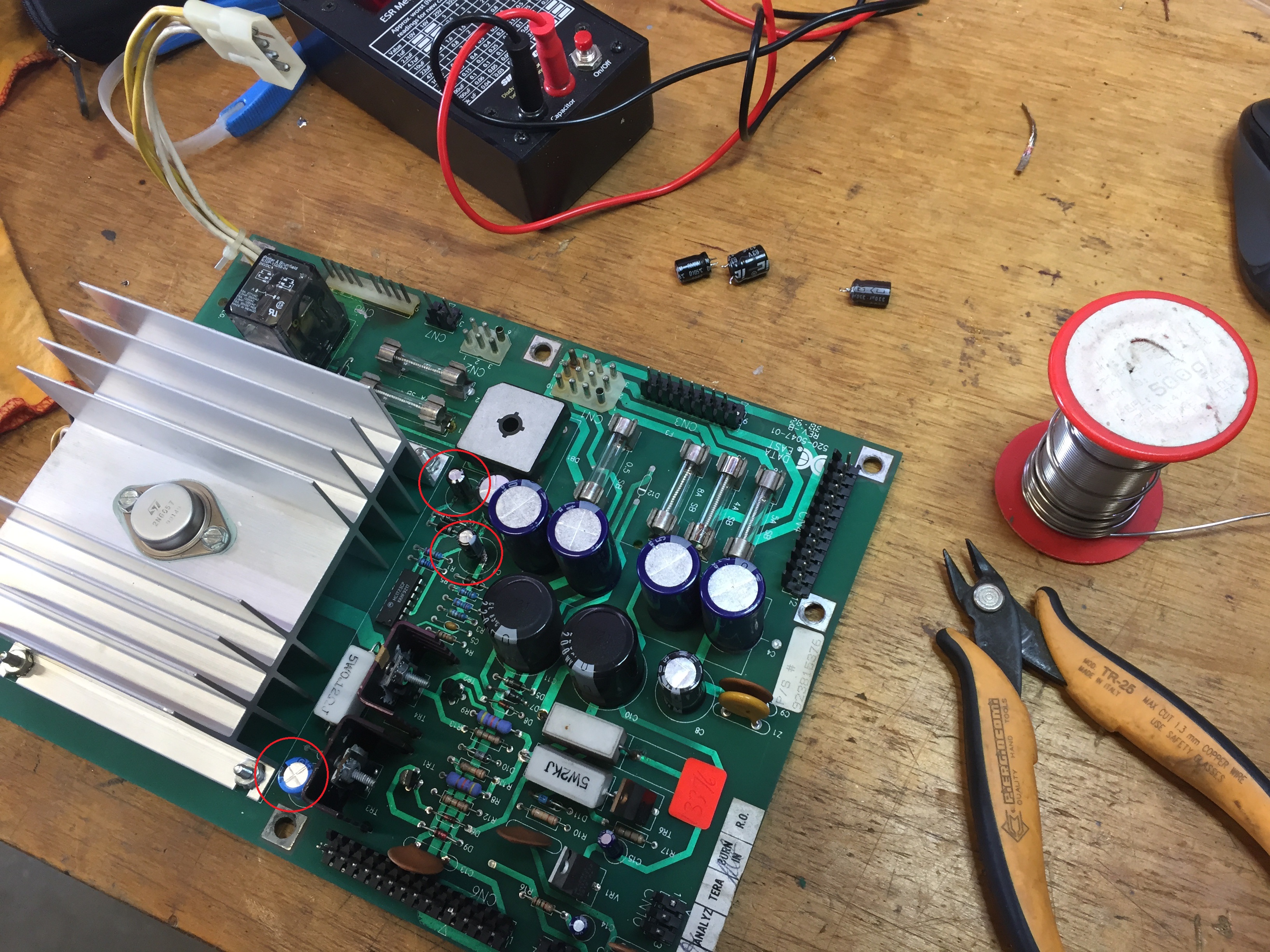
I powered down and unplugged the 5v connector from the CPU board. Re-applied power and measured the 5v test point on the power supply board (520-5047-00). No good, about 4.1 volts. I measured the +ve and -ve 12 vold test points and these were fine. A quick review of the schematic shows that the 5 volt rail is derived from the 12v rail, so having a healthy 12v was a sign that the 5v regulator circuit was at fault. Key to this circuit is the MC1723CP chip (IC1). Pins 11 and 12 are the input power to power this chip. I measured voltage here and found only 6v. I reviewed an online PDF of the MC1723CP. Its minimum input voltage is 9.5v.
No surprises here. I have seen this problem a number of times on Data East and Sega machines. Capacitor C2 is responsible for providing power to IC1 (with the diodes D2 and D3 and capacitor C3). C2 however appears to not fair well with time. I suspect being located so close to the heat sink is a likely reason for these capacitors to fail so often.
Taking the PCB back to my workshop I quickly swapped out C2, C3 and C7. All completely shagged! Whilst this board has been serviced in the past ( I see some nice new Nichicon capacitors in the high voltage side), the capacitors on the low volts side were original and dry as a dead dingo’s donger.
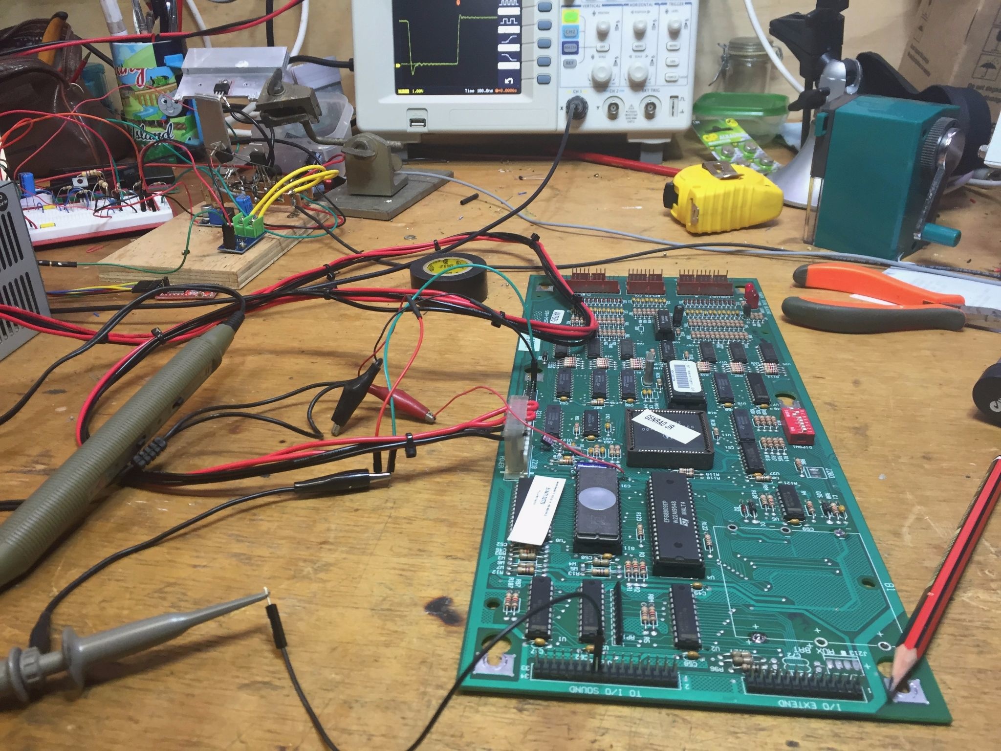
I returned the board to the machine after testing it on a bench AC power supply, and it booted lovely. The 5v rail sitting just where I like; a hair above 5 volts. More importantly, the machine boots up and no more problems with blowing fuse F5.
One question remains. Blowing fuse F5 was a result of the CPU sending “bogus” signals to the outputs. The blanking circuit is designed to protect against this. I’ll have to spend some time studying the schematics, but I suspect the low 5v line must have interfered with the correct operation of the blanking circuit.
Anyhow, the machine was returned to service just in time for the Saturday evening pinball league. We gave the game a quick once over then installed the new updated ROM set from http://www.pinballcode.com/. ( V5.00 unofficial ). I was skeptical, but must must say I really enjoyed the new game features and scoring. I haven’t played anywhere near enough to give a definitive thumbs up, but the games we played were in my opinion a better balanced scoring than the original game.