With the advent of repaired or replaced Solenoid Driver boards (SDB) some people experience an unreliable “reset” on their original Bally or Stern MPU board. I hope to describe here a cause and remedy for this situation.
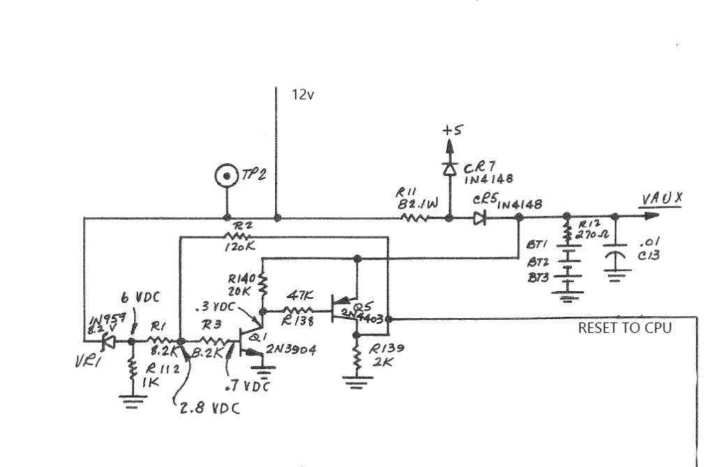
Valid Power vs Reset. At the heart of the problem is the intention of the circuit shown above. Its functionality is to hold the CPU in reset (high) until the power supply reaches a “valid power” state. This is a fundamentally fine objective, but it conflicts (somewhat) with the requirements of CPU reset requirements.
The CPU requires the reset line to be held low for at least 8 clock cycles after 5v power rail has reached 4.75v.
Inspecting the Bally Stern circuit, we see no capacitors in the design to enforce the minimum time needed in reset. The reset signal is held low until the 12volt rail exceeds 8 volts. The designers have assumed a steady ramp up of the 12 volt supply rail and a fast stabilisation of the 5 volt regulator will provide sufficient “Reset low” time for the CPU. Indeed they are assuming a precise relationship between the 12volt ramp-up time and the speed of the 5 volt regulator.
With modern replacement regulators, new power supply capacitors, switch mode power supplies and the likes, the precise timing of the reset circuitry can no longer be guaranteed.
Resolution
Install a dedicated reset management chip like the Dallas DS1811.
These reset chips include both a valid power detection circuit and a timing element to ensure the reset line is held low for a minimum of 150mS after a valid-power condition.
Installing DS1811-10
Installing a DS1811-10 is relatively simple on the Stern MPU-100 and AS-2518-17.
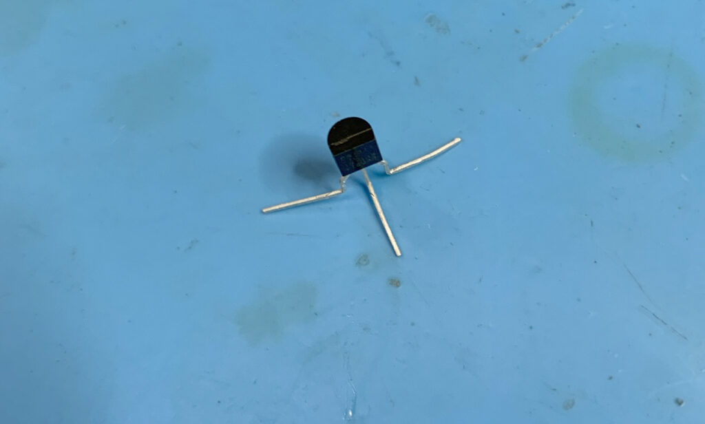
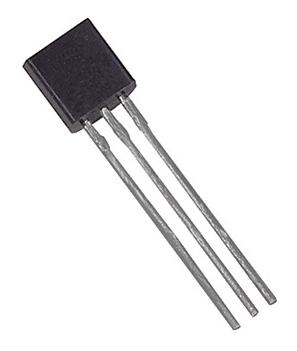
The DS1811-10 is a 3 pin package (TO-92) that resembles a transistor. It can be installed onto the MPU board easily requiring requiring the removal of only three components from the original circuit.

Step 1:
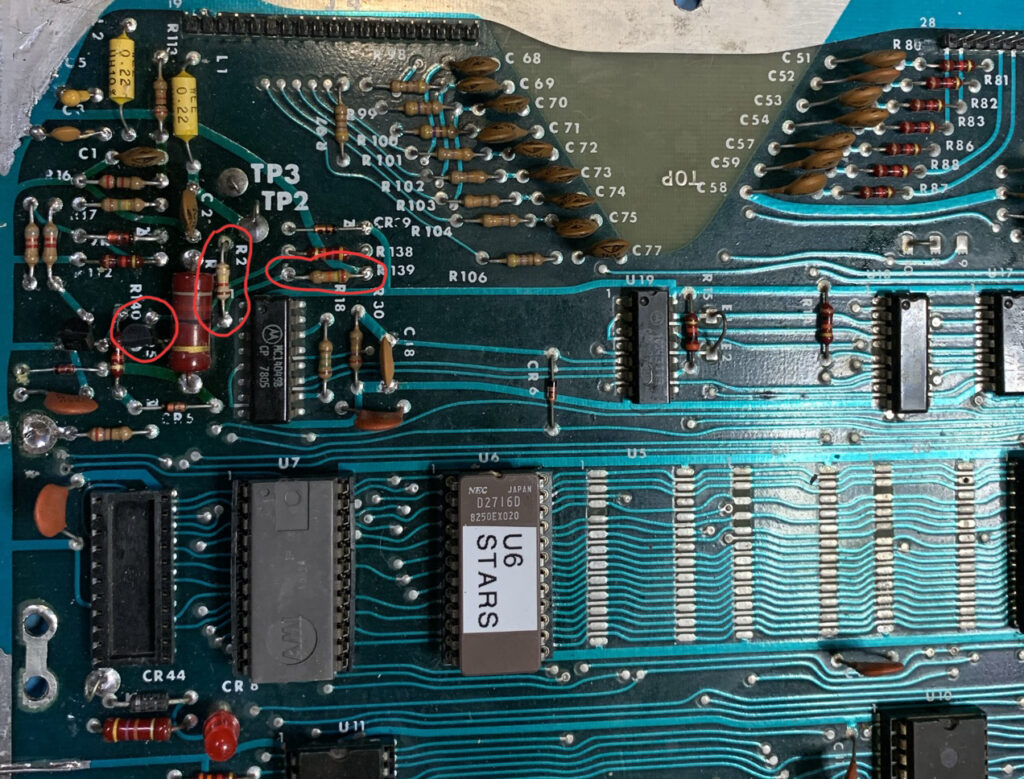
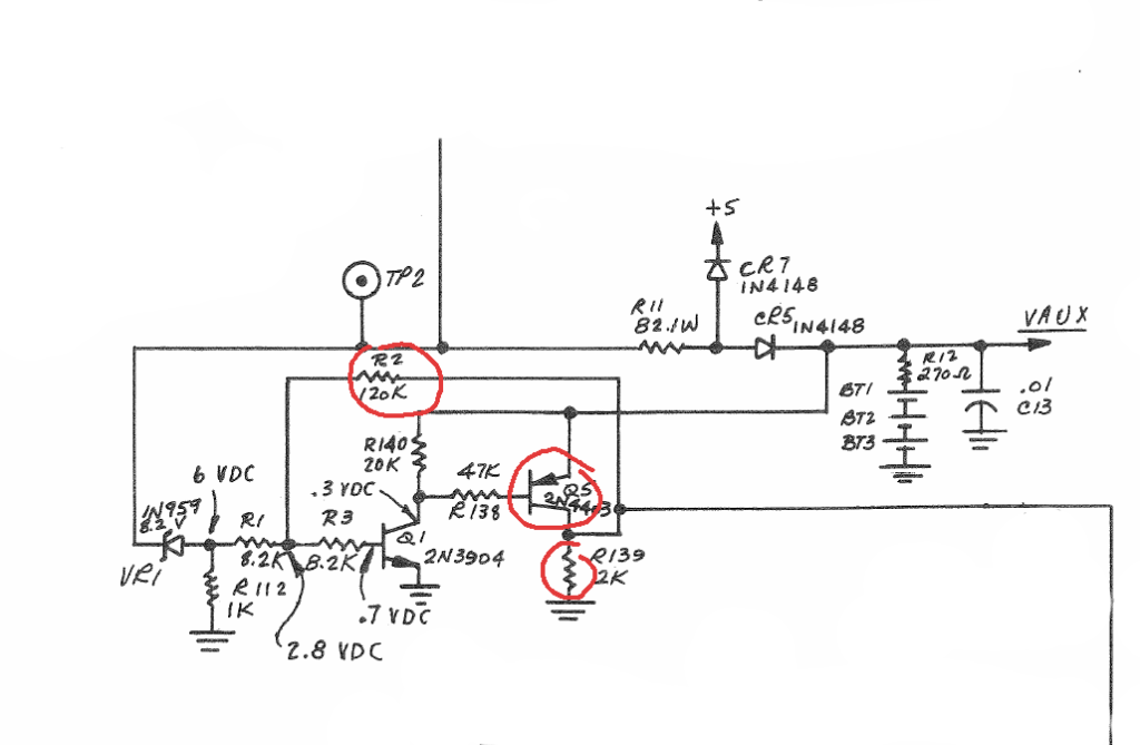
Remove resistors R2 and R139. They may be removed with a soldering iron or just snipped from the top side of the board.
Step 2:
Remove transistor Q5. Use either a soldering iron or merely snip the legs from the top side of the board.
Step 3:
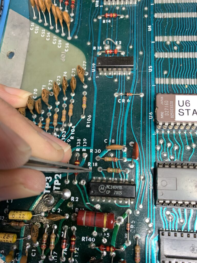
Scrape a section of the solder resist away from the tract near R139. (See photo)
Step 4:
Bend the legs of the DS1811-10 as shown in the photo.
Step 5:
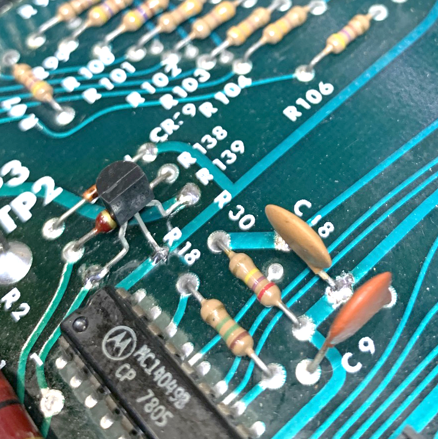
Solder the DS1811-10 onto the PCB from the top side of the board. (See photo)