Tangles presents a board to replace Stern TA100 and Bally AS-2518-18 rectifier boards. The original boards suffer from undersized rectifiers, over-heating and high current stress in the through-hole plating of some connectors.
With the introduction of the TPP-1025 replacement board we present the following features:
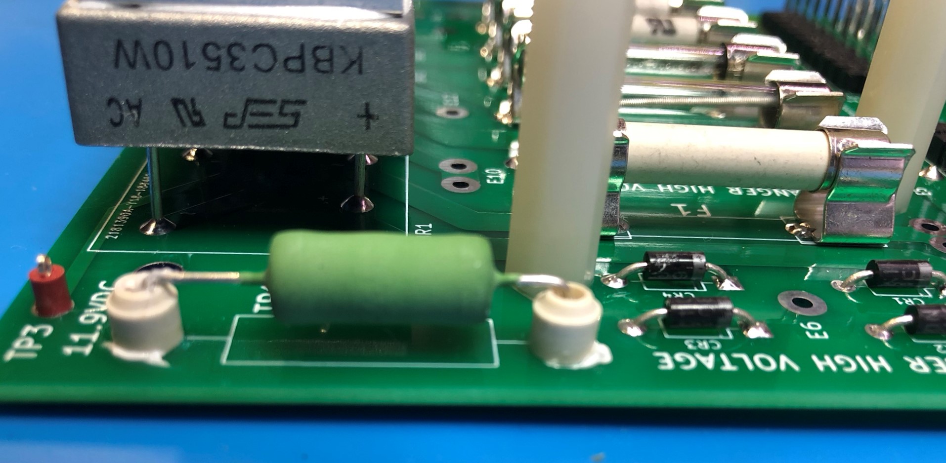
- 3 high current rectifiers (35A)
- Heatsinks installed on all three rectifiers.
- Quality Molex branded connectors.
- All high current paths have expanded traces.
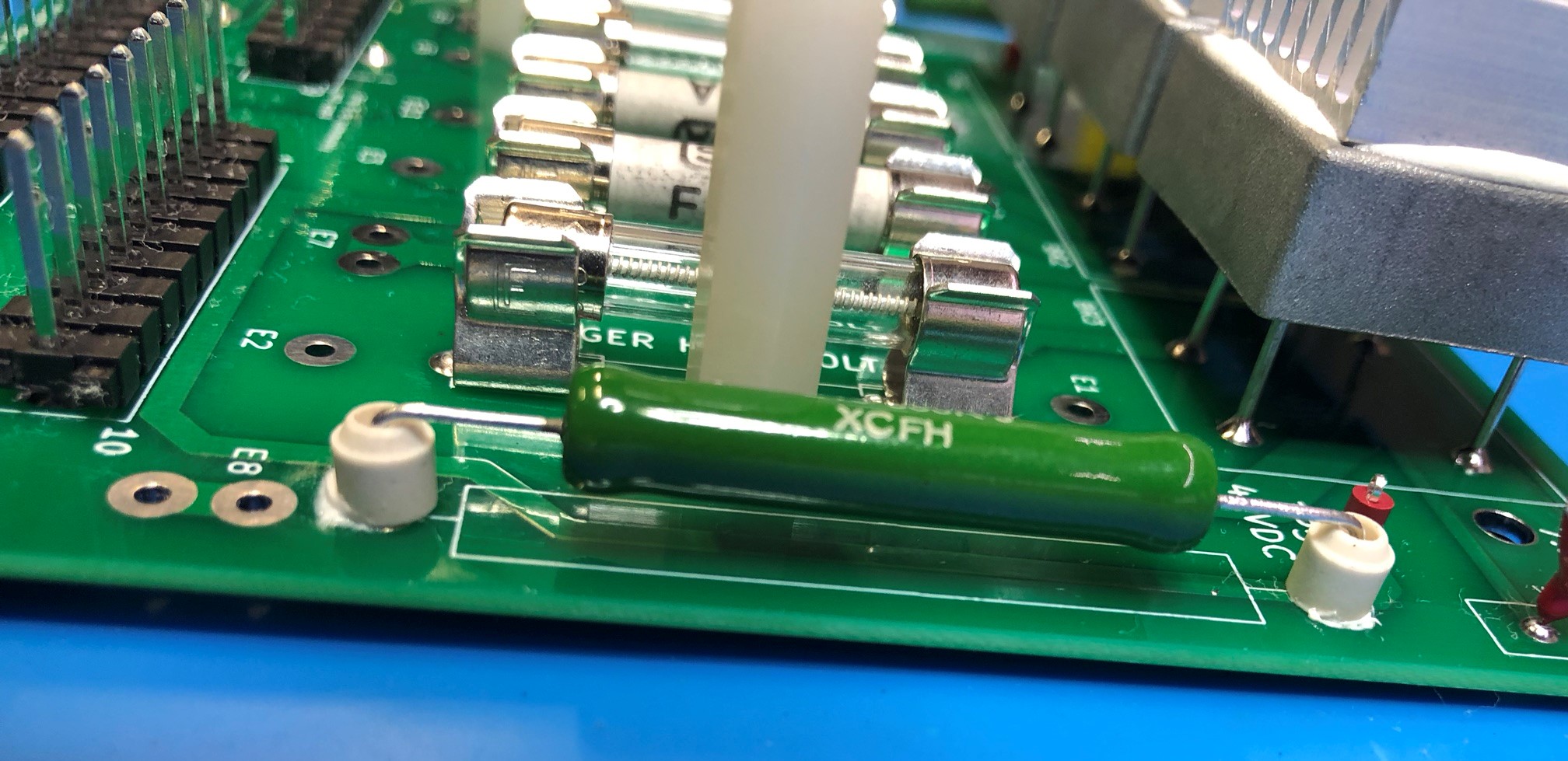
- Ceramic stand-off mounts for the high power resistors.
- Heavy wire to route current from the bottom of the PCB to the top, not relying on the through hole plating.
- Screw terminal for enhanced grounding.
- Multiple solder points transformer pins E7, E8, E9 and E10 for machines that have multiple wires at these points.
- 9th pin added to J1. This makes it compatible with machines need the extra wire.
- Littelfuse and Siba brand fuses.
- Littelfuse fuse branded fuse clips and MOV.
- Quality branded wire wound power resistors.
- Vitreous enamel 10w resistor for exceptional heat tolerance.
- Includes poly-carbonate safety shield
Downloadable manual available here: https://shedspace.net/TPP/TPP-1025-Rectifier.pdf

WARNING: Lethal voltages are present in Pinball machines and on this board. This service procedure is suitable for qualified persons only.
Tools Required
To successfully install this part you will need the following tools:
- Moderate to high power soldering iron.
- Multimeter
Compatibility
Bally Games:
Black Jack, Dolly Parton, Eight Ball, Evel Knievel, Freedom, Frontier, Future Spa, Harlem Globetrotters, Hotdoggin’, KISS, Lost World, Mata Hari, Mystic, Night Rider, Nitro Groundshaker, Paragon, Playboy, Power Play, Rolling Stones, Silverball Mania, Six Million Dollar Man, Skateball, Space Invaders, Star Trek, Strikes & Spares, Supersonic, Viking, Voltan
Stern Games:
Ali, Big Game, Catacomb, Cheetah, Dracula, Dragonfist, Flight 2000, Free Fall, Galaxy, Hot Hand, Iron Maiden, Lectronamo, Lightning, Magic, Memory Lane, Meteor, Nineball, Orbitor One, Pinball, Quicksilver, Seawitch, Stargazer, Stars, Stingray, Split Second, Ted Nugent, Trident, Viper, Wildfyre
Installation
Installing a TPP-1025 Rectifier board is a project requiring moderate to high levels of skill. The complexity of the installation task is due to the soldered required for wires that connect the board to the transformer.
A moderate level of soldering skill is required to install this board. The 18 Gauge wires from the transformer require a moderate to high powered soldering iron to remove them from the old board and re-attach them to the new.
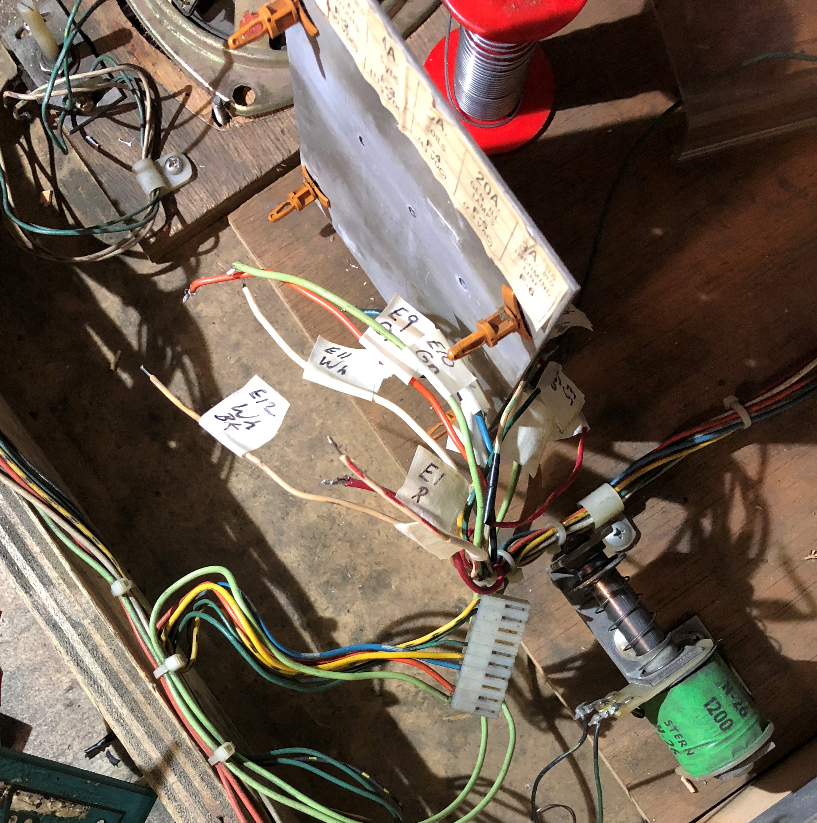
When installing this board is is important to identify the transformer wires soldered to the back. I present here a table of standard colours that may assist in the wire identification. I encourage installers to label each wire as they are removed from the old board so they do not get mixed up.
![]()
The wire colours provided should be taken as a guide only as machines may have differences, or may have had wires replaced with a non standard colours.
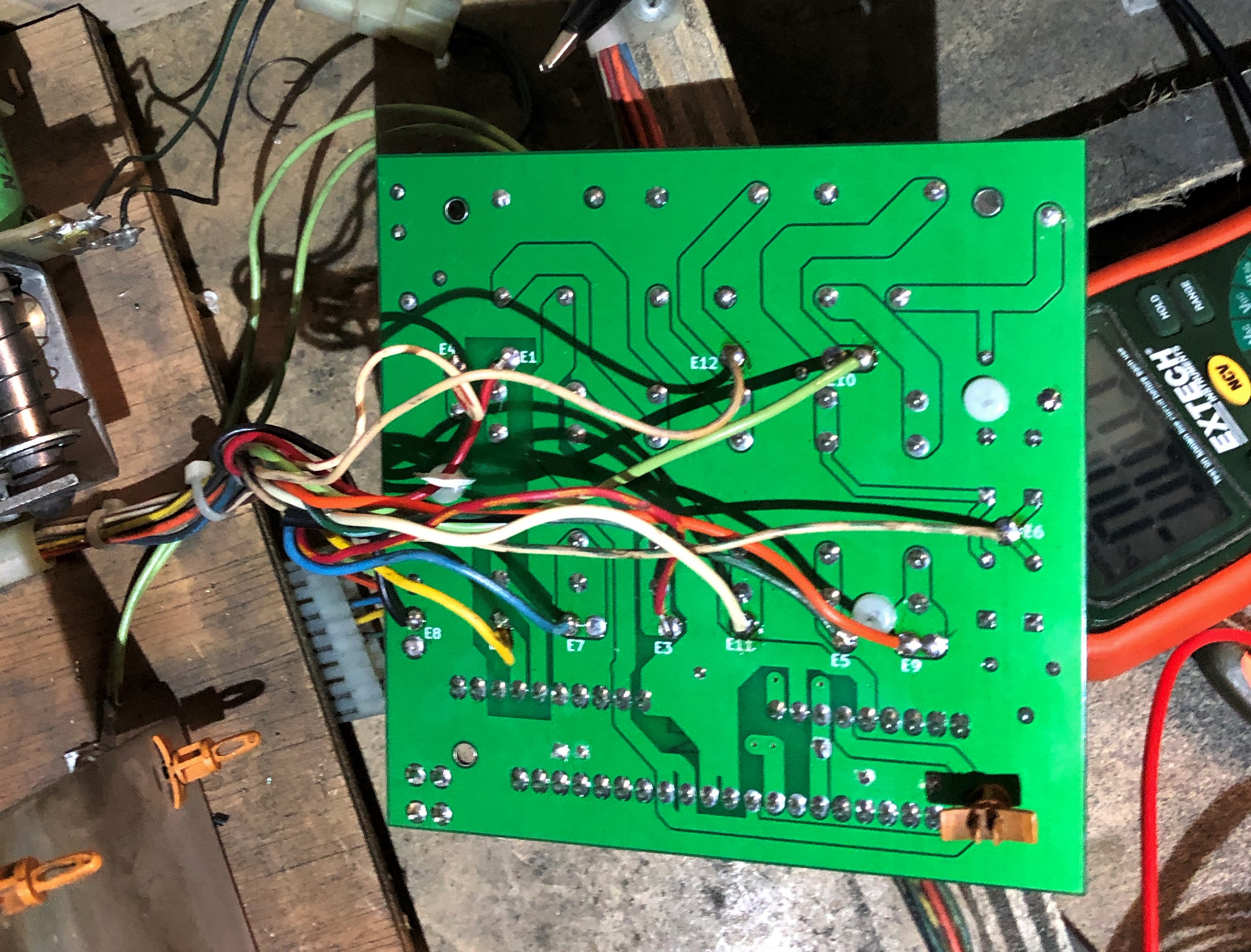
Here’s a photo of my old TA100 board with the transformer points identified:
![]()
Having removed each wire, a label is attached using masking tape. This ensure wires are not mixed up in the transition.
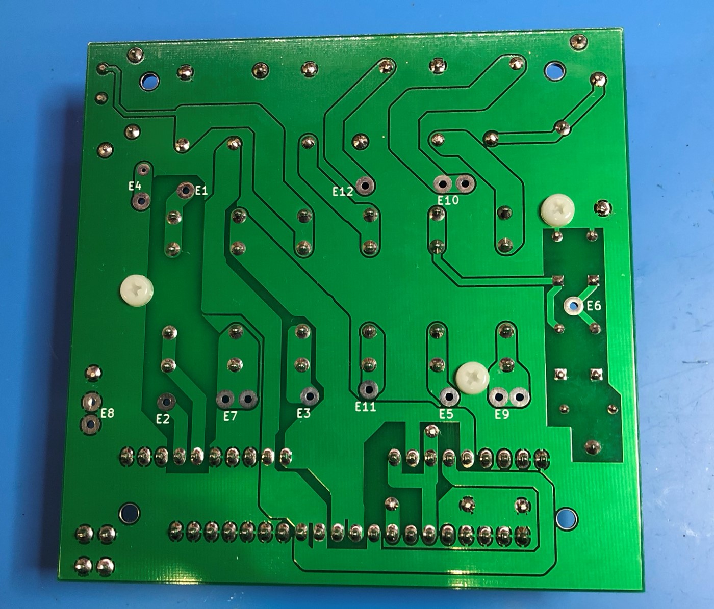
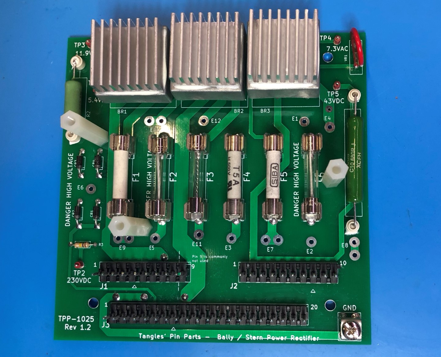
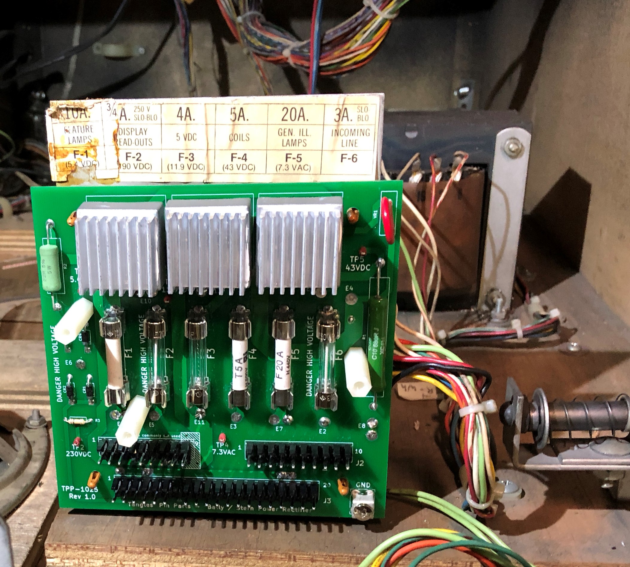
The new board (TPP -1025) has the transformer mount points marked on the front and rear of the PCB.
It is recommended the wires be inserted into the holes and soldered on both sides of the board.
The new board is now mounted onto the metal support bracket. Its time to perform powered testing. The following test steps are recommended.
- Ensure mains power is disconnected from the machine before connecting connectors or multimeter.
- Plug in J2 only.
- Attach a multimeter between the ground terminal (bottom right) and test point 1 (TP1).
- Plug the main power in and switch the machine on.
- Verify the voltage. Note that voltages may read up to 20% higher whilst power supply is not under load. This is normal.
TP1 5.4V DC
TP2 230V DC
TP3 11.9V DC
TP4 7.3 V AC
TP5 43V DC
WARNING : Be sure to remove power from the machine when moving or removing multimeter test leads.
FUSES
Standard fuses supplied with the TPP-1025 are:
F1 10 Amp fast blow.
F2 750mA slow blow.
F3 4A fast blow.
F4 5A fast blow.
F5 20A fast blow.
F6 3A slow blow.
Check the manual of your particular machine for possible variation on this fuse configuration.
Molex Connectors
It is highly recommended that connectors be replaced on the wiring harness for J1, J2 and J3. This should entail replacing the plastic connector shells and re-crimping new terminals. Molex Trifurcon connectors (Mfr. Part No. 08-50-0187 ) are recommended.
J1 Playfield.
8 way Molex KK 396 (series 2139) housing. Molex part 09-50-3081.
Note that some machines use a 9 way connector in this position. Machines with an 8 way J1 connector should plug into the left most pins (Pins 1 to 8) and leave pin 9 on the board unconnected.
J2 Cabinet
10 Way Molex KK 396 (series 2139) housing. Molex part 09-50-3101.
J3 Back Box
20 way Molex KK 396 (series 2139) housing. Molex part number 09-50-3201.
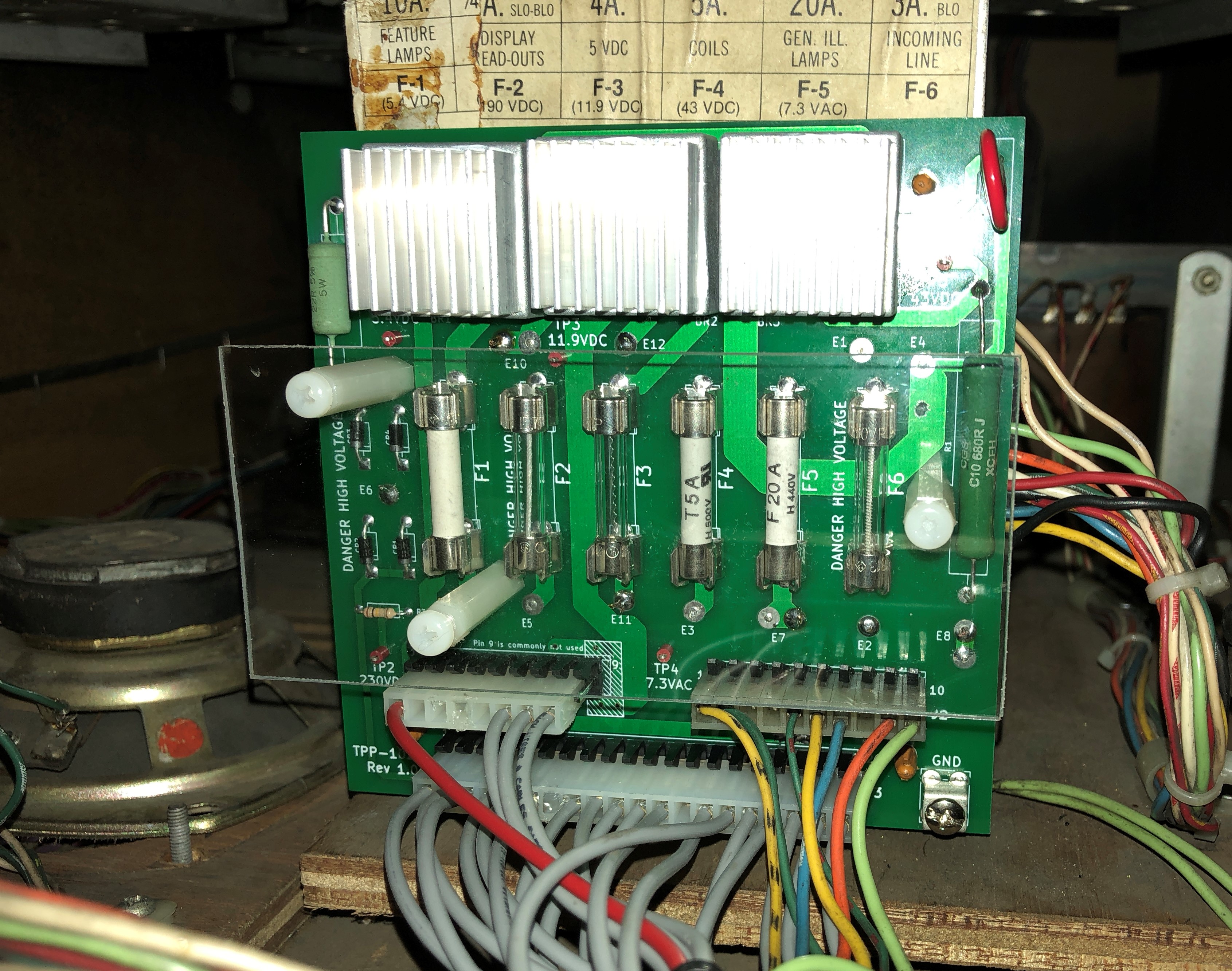
Safety Shield
The picture below shows the boards safety shield installed.