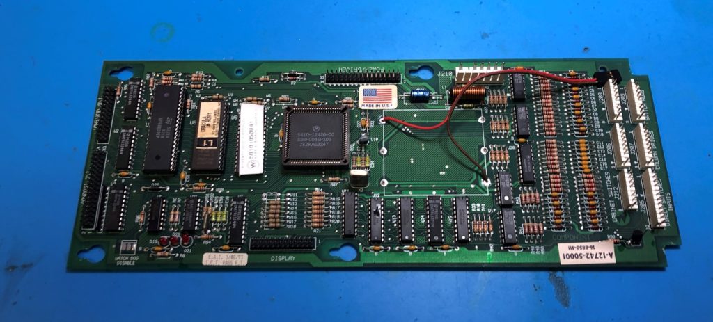
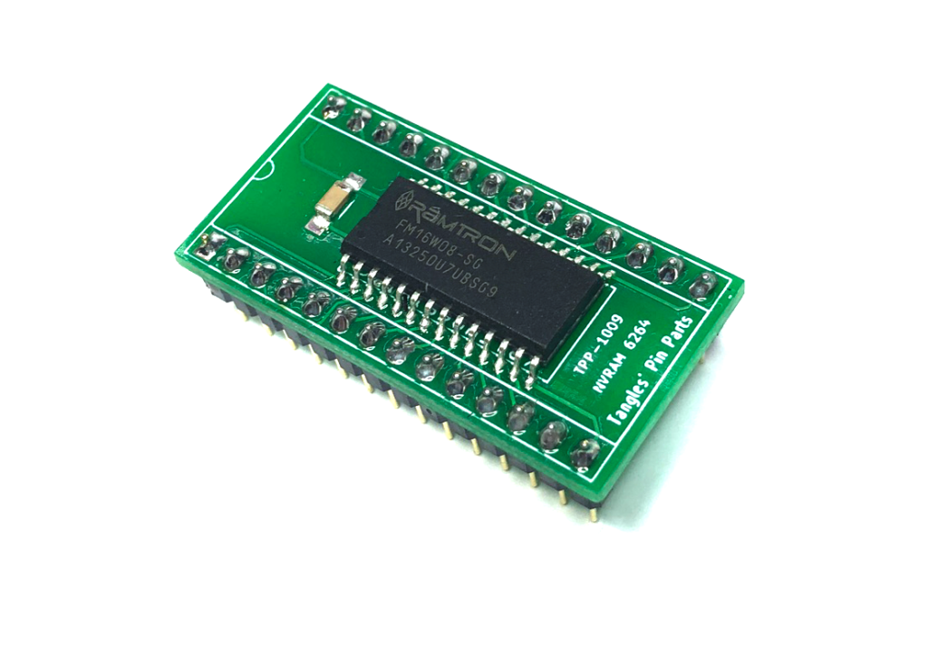
I’ve started installing Tangles TPP-1009 NVRAMS in all my Williams machines.
Installation of an NVRAM module into a Williams WPC board should be regarded as an operation suitable for people with advanced soldering skills only. The WPC circuit board do not have sockets on the 6464 memory and thus de-soldering is needed. Add to this the tiny hair-line traces on the WPC PCB, extra care is needed to ensure traces are not broken or damaged.
I’ll present here the tips and techniques I use, but rest assured these are better guides available for this advanced procedure.
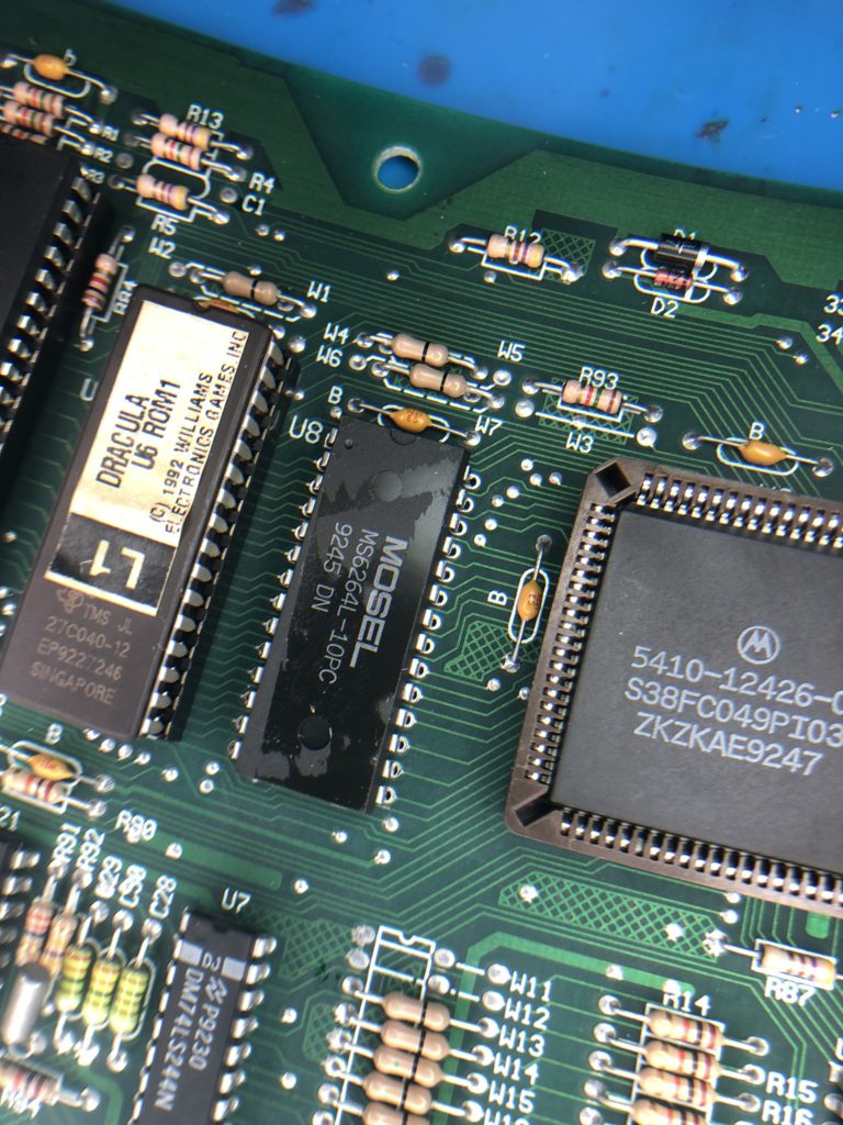
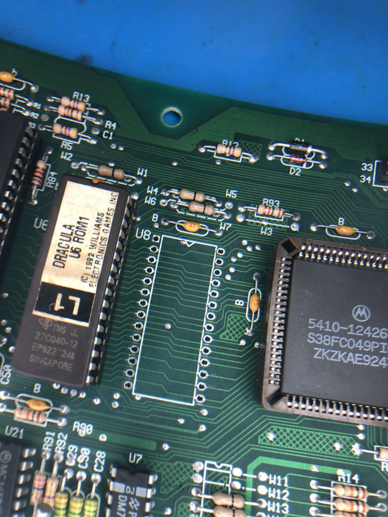
- The 6264 RAM chip is located next to the rectangular PLA chip. It is typically covered with a warranty-void-if-removed sticker.
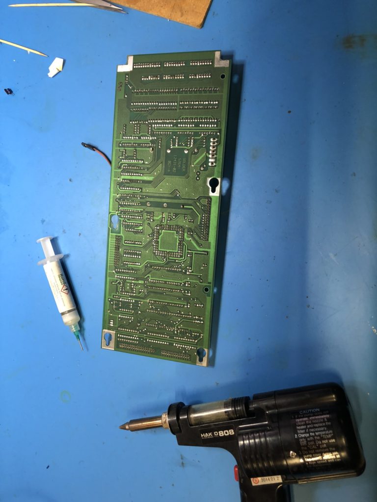
- When de-soldering, I use a Hakko 808 de-soldering tool. Ensure you have the temperature of this tool turned down relatively low and high temperatures will lift the fine traces very quickly. I suggest 300 deg C.
- I de-solder with the aid of a good quality gel flux. I prefer non activated flux as it is safe to leave some residue on the PCB. (Assume your cleaning efforts are not going to be perfect.) I use ChipQuik SMD291 flux.
- When de-soldering, use light pressure and try not to let the tool tip press against the pad.
- When de-soldering, use a circular wiggle motion as you activate the suction trigger. This helps remove solder from all around the pin.
- When de-soldering allow enough heat up time before suction is applied. Ensure the solder is well and truly molten on both sides of the PCB.
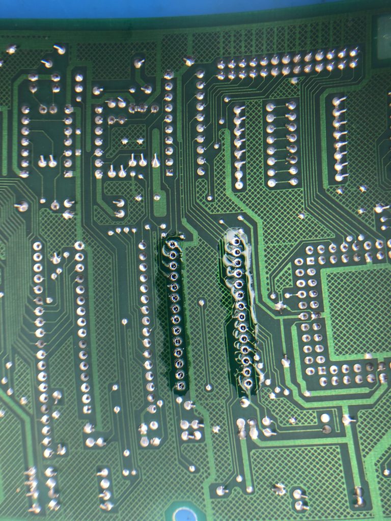
- After all pins are de-soldered, inspect all holes with a magnifying glass. Inspect both sides of the board to ensure all the solder has been removed.
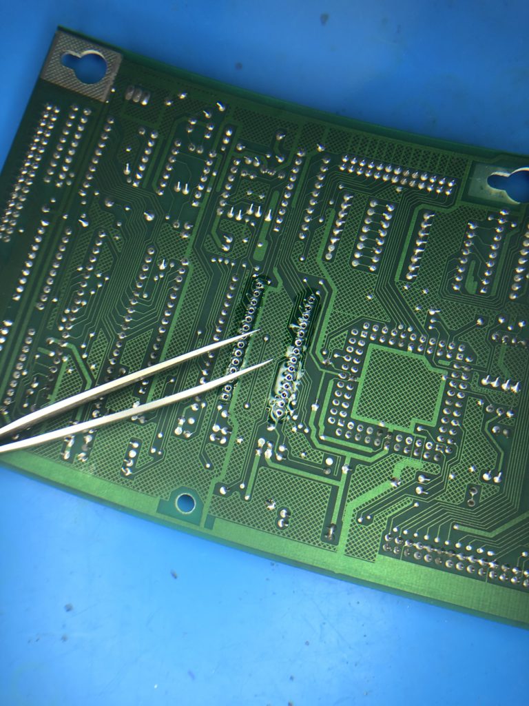
- I use tweezers and individually wiggle the chip ping to determine if they are still stuck to the sides of the through-hole plating. As you wiggle a pin you may hear a tiny cracking sound as the pin breaks free of the side-wall.
- When all pins feel loose, gently start to wiggle the whole chip whilst watching the pins on the underside of the board. I am looking to identify any pins not moving when the chip is wiggled. These pins may need to be wiggled with the tweezers more or de-soldered a second time.
- If I need to de-solder a second time, I first add solder to the pin. De-soldering works best when there is plenty of solder to remove. It works poorly when there is only a residual amount of solder in the joint.
- When the chip is truly de-soldered, it should come out of the board with little pressure. NEVER pry the chip from the board!
- When the chip is removed, carefully inspect the top and bottom of the PCB to ensure no damage has been made to the traces.
- Clean the top and bottom of the board with isopropyl alcohol.
- I apply a light smear of flux to the top side of the board. This flux will help the solder to flow from the board underside to the topside and adhere to the pad on the topside of the board.
- Install a 28 pin socket. Ensure the notch on the socket matches the notch on the PCB silk-screen.
- Solder the socket from the underside of the board. Ensure your soldering iron is not too hot. I set my iron to 300 deg C. This is a little lower than I normally use (320C), but is necessary to ensure the tiny traces are not cooked too much and lift from the board.
- When soldering, I allow the pin to heat up. I apply solder. Then I wait until I can see the solder level dip (drop) as it flows to the top side of the PCB. I then add a small amount more solder. All of this should take place in less than 2 seconds.
- When all pins are soldered, I carefully inspect the board underside.
- I flip the board over and inspect the top side to be sure solder has flowed from underneath to the top side. This is easily seen when using a turned pin socked (round holes), but can still be seen if you are using a typical double wipe socket.
- When I am happy with the soldering, I use a continuity tester and beep out every pin of the socket. I do this testing from the top side of the board.
- Most pins are easy to beep as they go to a similar pin on the neighbouring EPROM.
- Some pins are difficult to beep as they go to pins on the PLA.
- Remove the old battery holder or wires if a remote battery was installed.
- It is time to clean the top and bottom of the board with isopropyl alcohol to remove any flux residue.
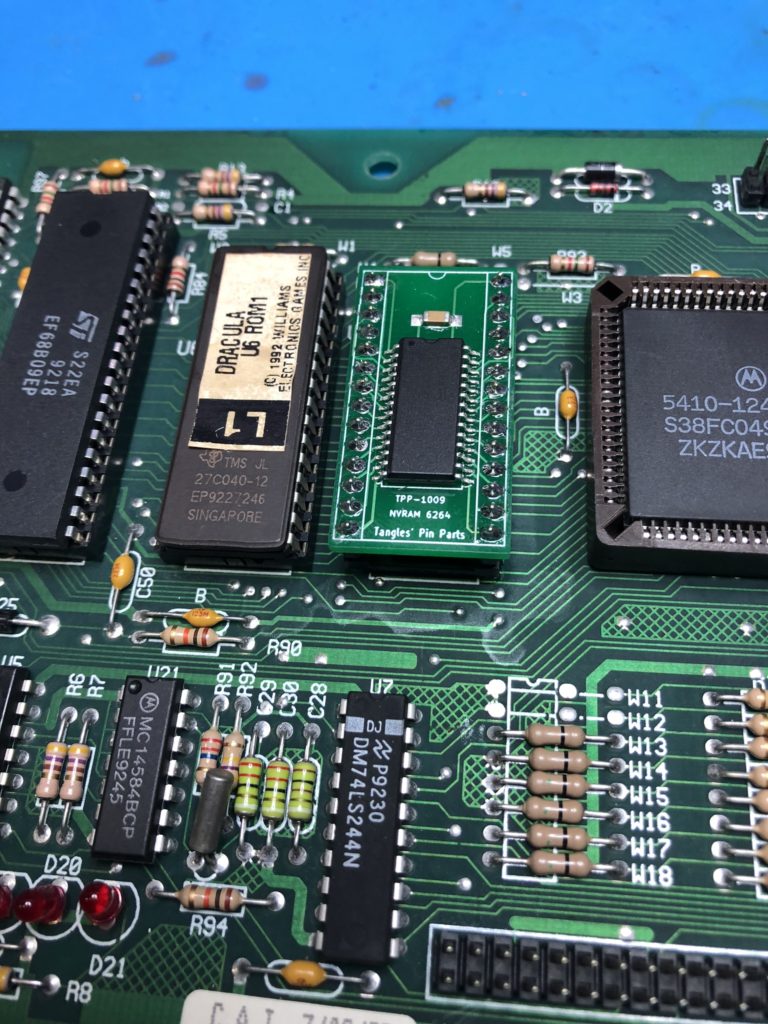
- The TPP-1009 NVRAM can be inserted into the socket.