Here’s some pictures of a Tangles NVRAM being installed in Lost World.
Category Archives: Uncategorized
Tangles’ Pin Parts – 7 Digit Bally Stern LED Display
Tangles has expanded the LED display product line to include 7 digit displays compatible with the old Stern and Bally parts A-645 7 and A5-2518-58.
The new units are available with Retro Amber LEDs, Stunning White LEDs and even Blue.
This unit comes fully assembled. No soldering is required. No modifications are needed to your pinball machine. This display units uses only the 5-volt supply. The high voltage supply is not used. This means this display will operate even if the high voltage circuitry is faulty or has been disabled.
Continue reading Tangles’ Pin Parts – 7 Digit Bally Stern LED Display
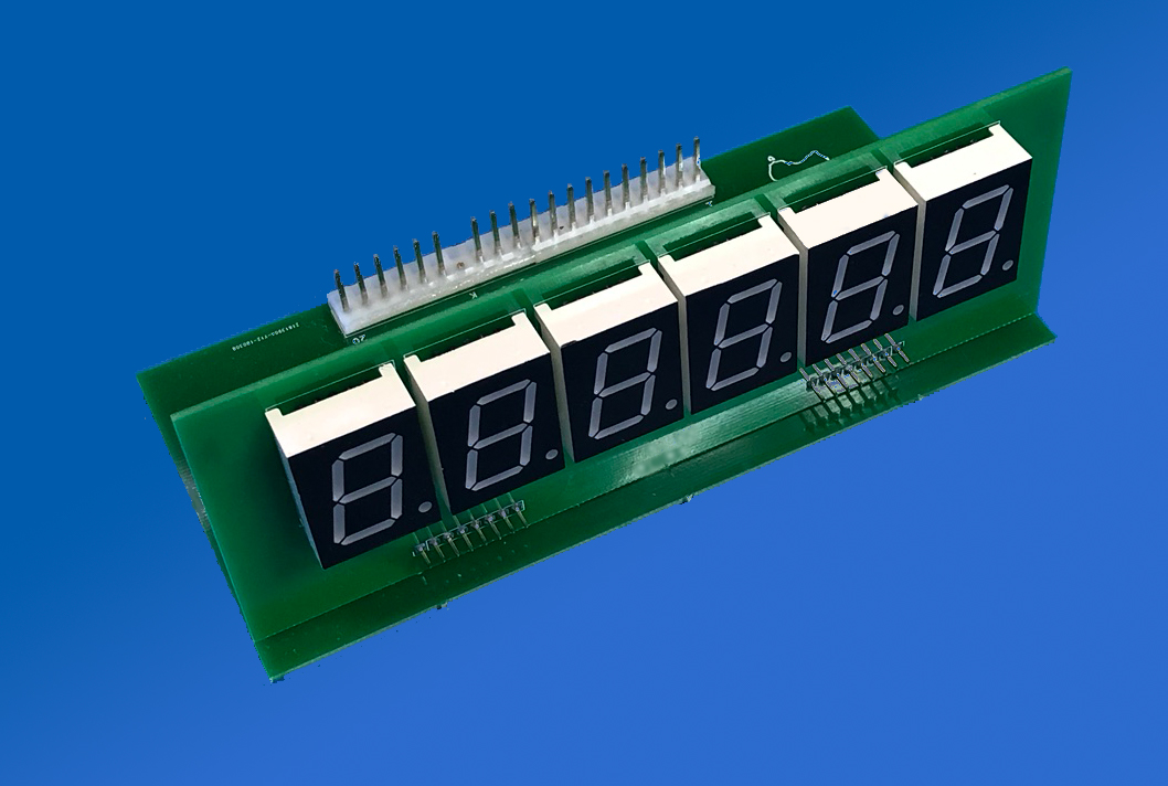
Tangles’ Pin Parts – 6 Digit Bally Stern LED Display
As a part of my pinball restoration endevours, I have designed a replacement 6 digit display module.
Continue reading Tangles’ Pin Parts – 6 Digit Bally Stern LED Display
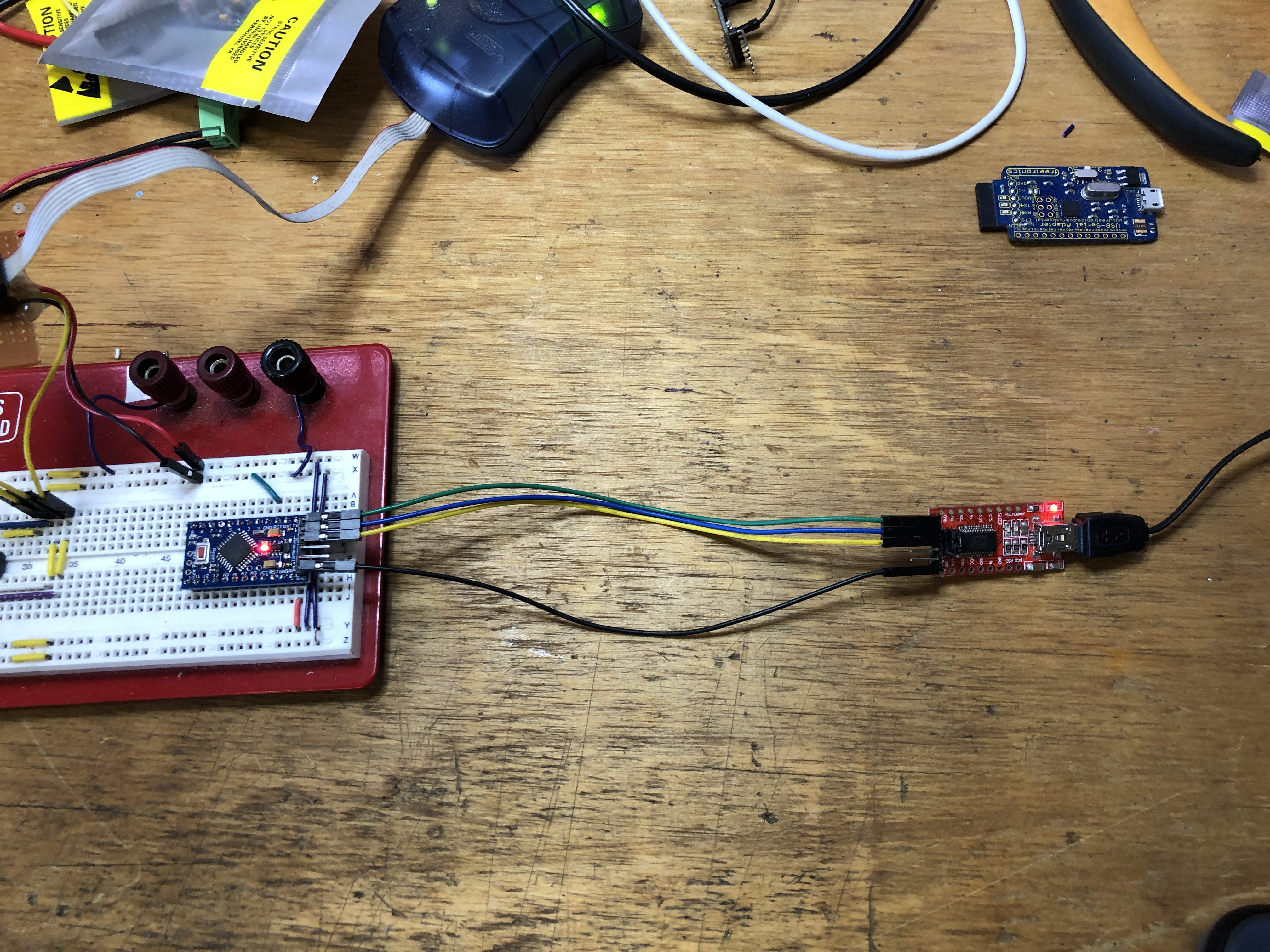
Programming (generic chinese) Arduino Pro Mini boards using an FTDI 232 USB Mini board.
When programming and not using the USB power to power the Pro Mini, wire it as follows:
Pro Mini               FTDI232

DTR ------------------ DTR
 TX ------------------ RX
 RX ------------------ TX
VCC                    VCC
GND                    CTS
GND ------------------ GND
Settings in the Arduino IDE are:
COM6 ( Varies… please check Device Manager … Ports)
Arduino Pro Mini
ATmega328P (5V, 16MHz)
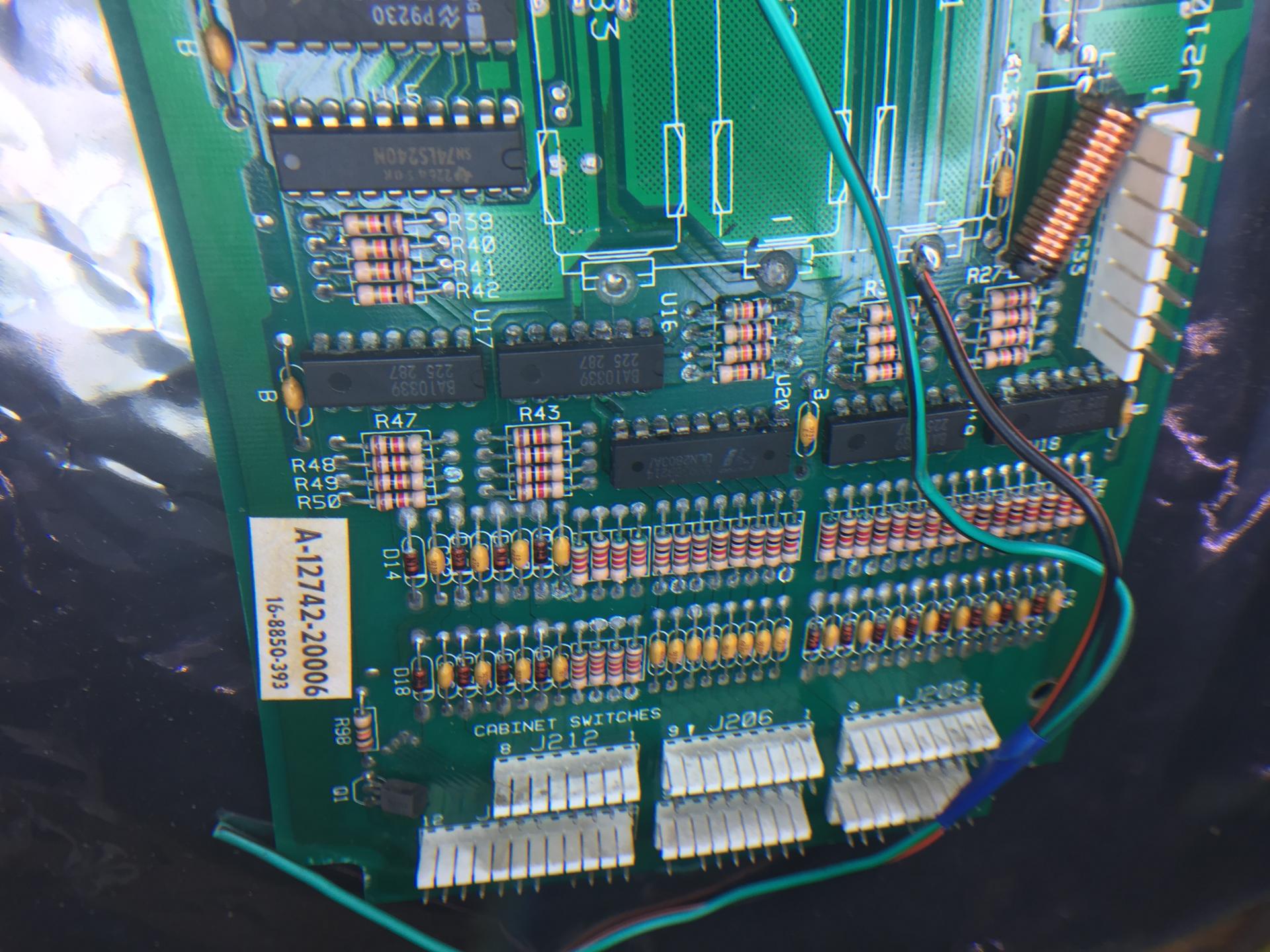
Bally Dr Who Repair – CPU Board with battery damage
Took on a fix job for another Dr Who (2nd in two months). Leaky batteries have left the game with a dead switch matrix.
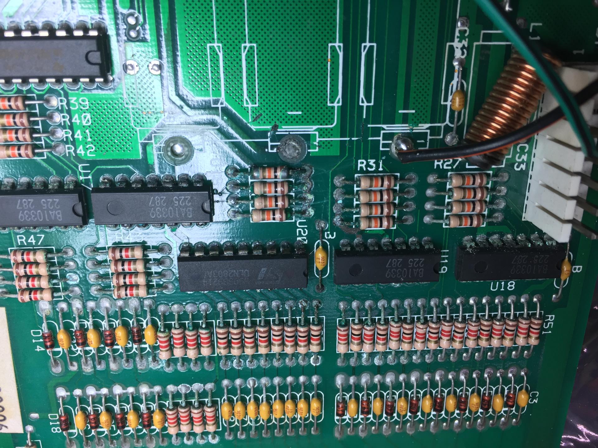
The initial inspection of the board did not look too bad, but as is ALWAYS the case, the bad stuff lies hidden underneath the components. I thought I would share some photos that illustrate how a board can look “nearly OK”, but have pretty serious damage.
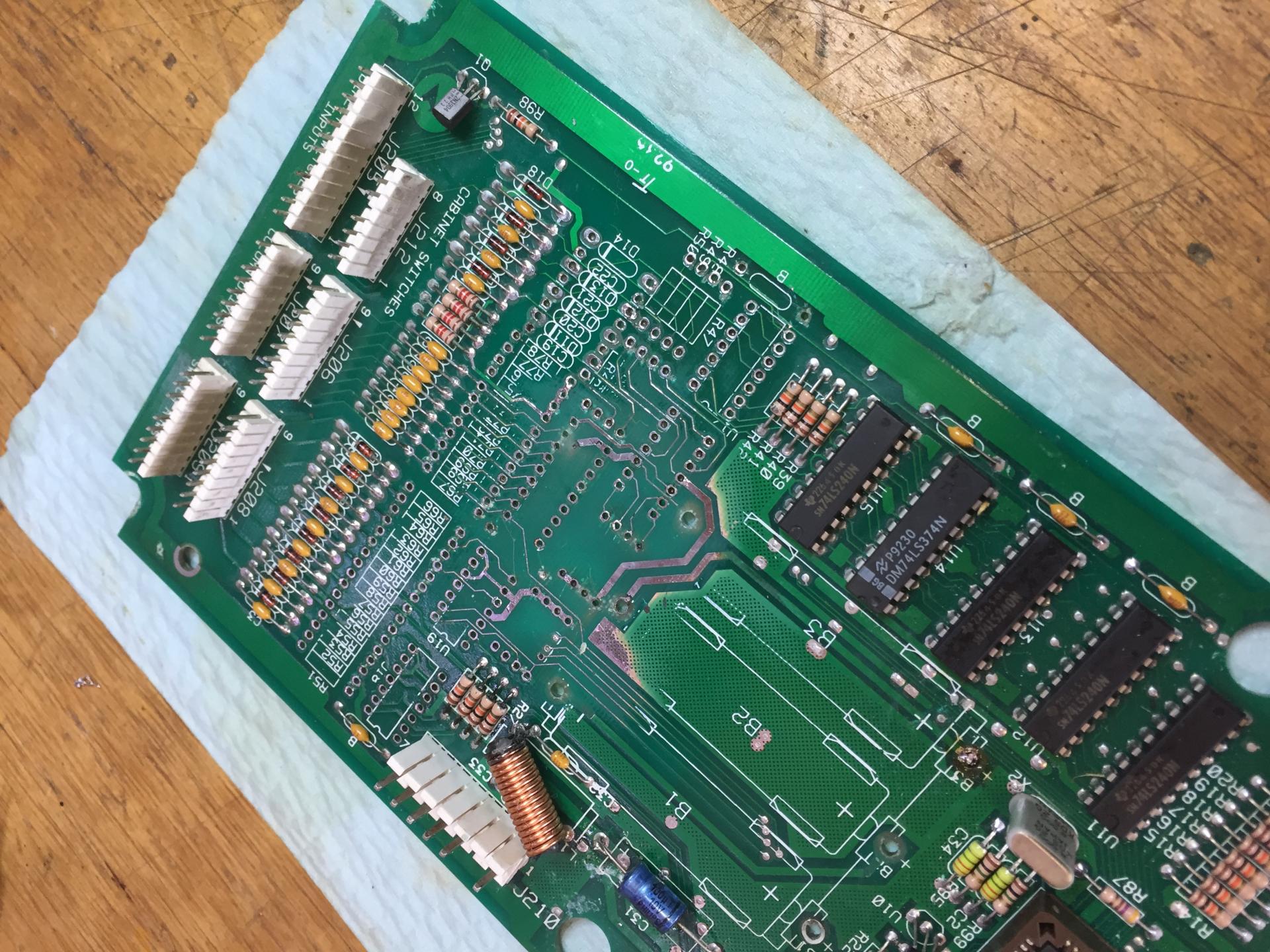
Here is the initial board looking … not too bad…
Now I have used a pointy set of side cutters to snip the leads of the parts to be removed and look what we find… Nasty crystalline schmoo!
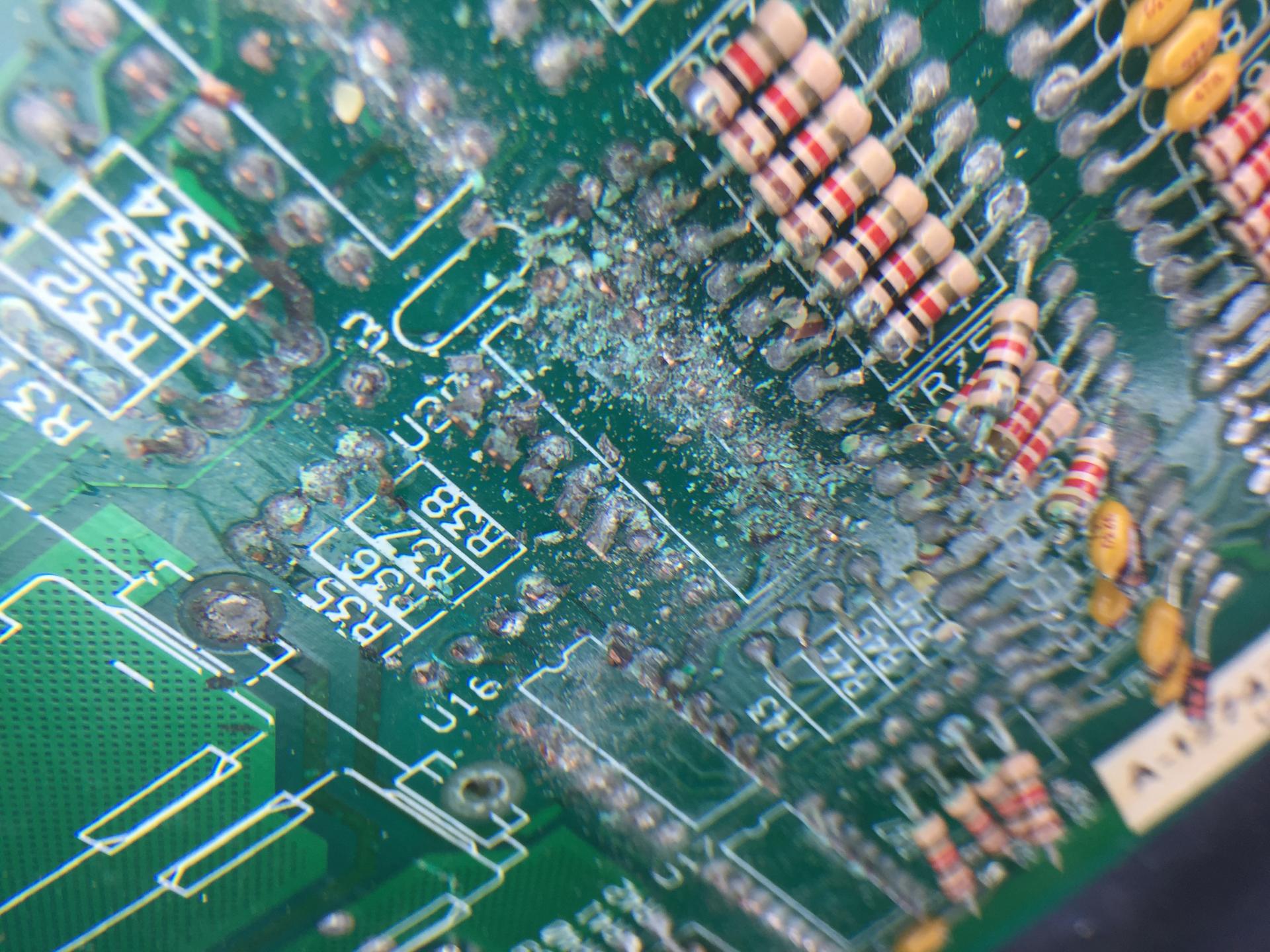
A lot of desoldering and cleaning with a mild acid solution and we can see the board is in a pretty bad state. Quite a few traces broken and a lot of “BLACK ROT” underneath the green solder mask.
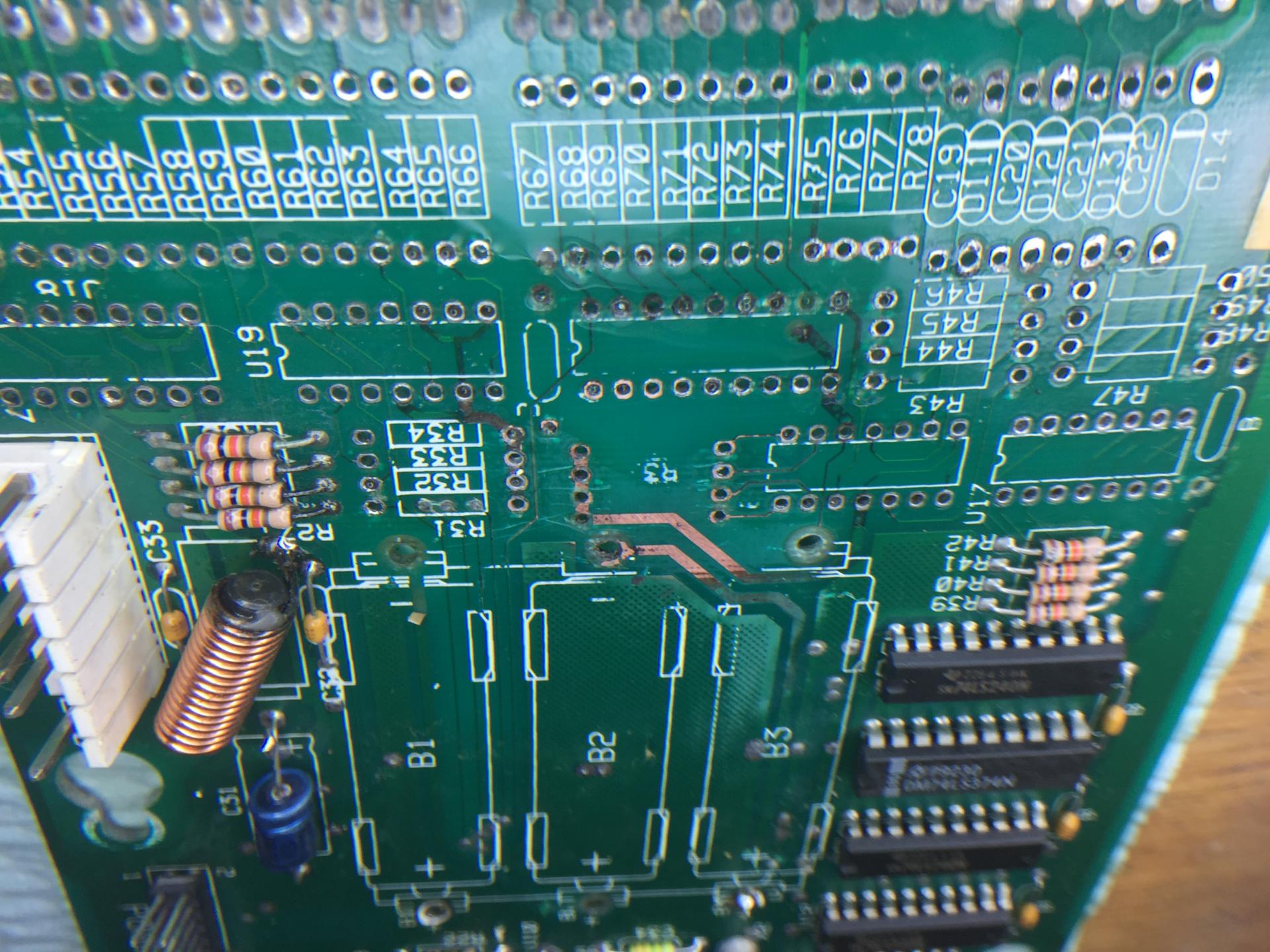
Some sanding with wet ‘n dry sandpaper and we can get some of the traces back to copper. I use a tonne of flux and solder wick to very lightly tin the bare copper. Enables me to see the broken and rotten traces better.
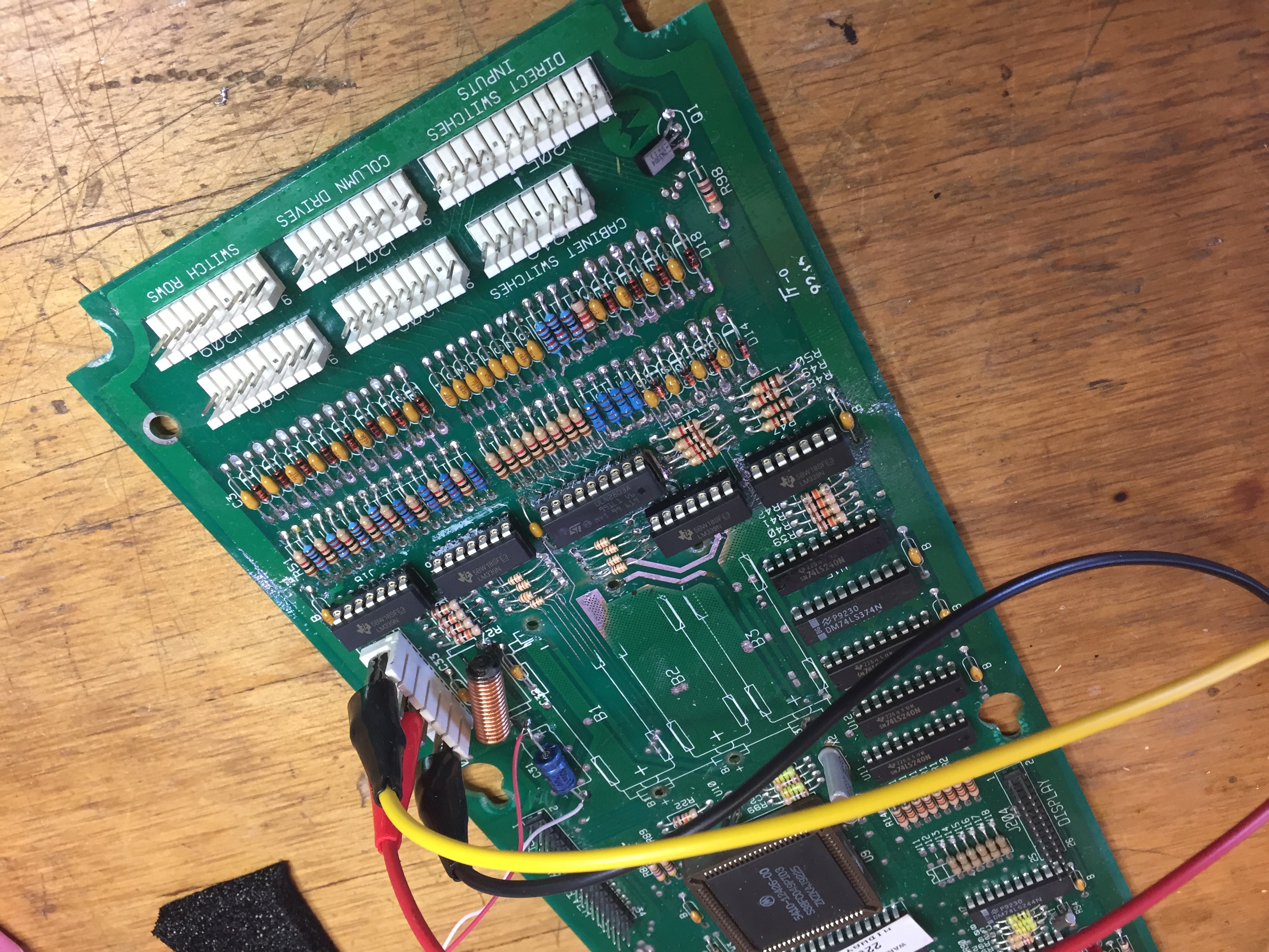
And here she is all back together and getting a bench workout. Using a logic probe and a diode to simulate the switches I can verify all columns and rows are working fine.
Next I installed into a “Creature from the Black Lagoon” (swapped the ROM) to verify the switch matrix all works and all other finctionality is as expected. Looking good. In the picture above I have applied a polyurethane conformal coating to the board for a bit of trace protection.
Next step is to pop it back in the original machine and give it a bash.
No photo, but I have added an off board lithium battery. I like to use the 1/2AA cells with a 2-wire molex to connect to the CPU. These 1.2AH batteries give the board a good operating life.
I’m a fan of the WPC circuitry. I think much of its design is highly commendable. I do wish they had used a little more copper on the traces and IC pads however. It takes skill and patience to remove these components without damaging the board. Add a bit of battery schmoo and the nature of the solder changes substantially. It is very hard to remove! Sometimes the process requires adding and removing fresh solder multiple time to get the old solder to flow. The biggest tip however is to use a good flux and use a LOT of it. (A bit like sex and lube … )
Data East Hook Fuse PPB F5 blowing. A strange journey leads to a well known problem.

A friend called with a problem on his Data East Hook. When he powers the machine on, it keeps blowing F5 on the PPB board. This fuse is in the AC side of the +50v power rail. Page 46 of the service manual was very helpful, showing that there are only a five high power solenoids on the +50v supply as well as the solid state flippers. My friend unplugged the flipper board and J7 of the PPB and noted the fuse did not blow. Plugging J7 back in blew another fuse. This at least showed us that the problem was not a bad rectifier or capacitor on the PPB nor was the problem in the flipper board.
I immediately suspected a blown (short circuit) driver transistor on the PPB, causing one of the 5 coils to be stuck on. I drove to his house and proceeded to measure the continuity of the big power transistors on the PPB. These are TIP36C. Whilst I have never had one of these fail on me in the past, a faulty or missing coil diode could certainly have caused one of these to fail. Alas, not so. All 5 transistors were testing good using the diode tester on my multimeter.
Ok, time to put some power onto the board and measure which coil is causing the fault. But how to do this without blowing fuses. I used an old trick of replacing the F5 fuse with a resistor. I chose a 5 watt 30 ohm resistor. Hooked up with alligator clips, this resistor would ensure that no more than a couple amps could flow in the 50v circuit even if there was a dead short.
I powered the machine on and noted two things, I could hear a coil buzzing for a couple of seconds and the CPU board was not booting.
A few more power cycles showed the Big-Kick coil was being activated for about 3 seconds when the power came on. It then stopped. This was surely the reason the F5 fuse was blowing. The coils on pinball machines are designed to operated for mere fractions of a second. Holding a high power coil on (with only a few ohms resistance) is more than the 5 Amp fuse can bear. The reason these circuits use slow blow fuses is that the instantaneous kick current pulled by the high power coils is greater than the fuse rating. But performed for such short durations, the fuse is safe. This machine however was holding the coil on for a good few seconds. Plenty of time for the slow blow fuse to circum to the pressure.
My attention now moved to the other fault on the machine. Not booting. The CPU board LEDS showed 5v and PIA illuminated. The blanking light was out. This means the CPU was not booting! Using my multimeter, I measured the 5 volt sully on the CPU board and got a very unhealthy 4.05 volts. No surprise the CPU board was not running. We were well under the typical minimum good voltage of 4.8v. ( I usually try hard to keep 5 volt rails a touch above 5 volts ).
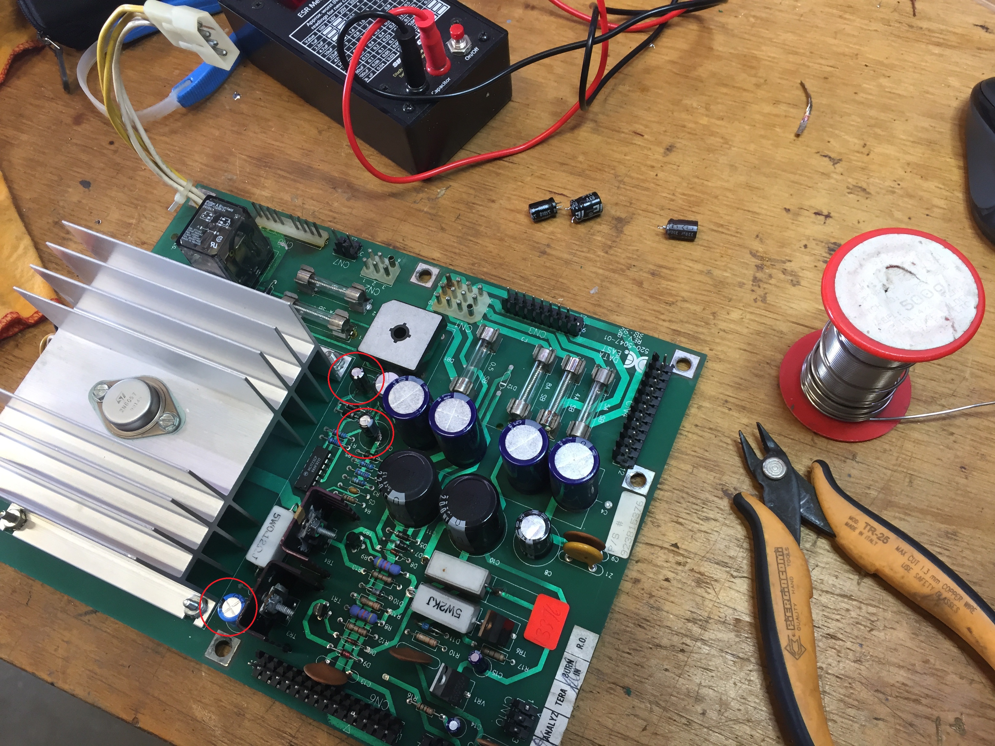
I powered down and unplugged the 5v connector from the CPU board. Re-applied power and measured the 5v test point on the power supply board (520-5047-00). No good, about 4.1 volts. I measured the +ve and -ve 12 vold test points and these were fine. A quick review of the schematic shows that the 5 volt rail is derived from the 12v rail, so having a healthy 12v was a sign that the 5v regulator circuit was at fault. Key to this circuit is the MC1723CP chip (IC1). Pins 11 and 12 are the input power to power this chip. I measured voltage here and found only 6v. I reviewed an online PDF of the MC1723CP. Its minimum input voltage is 9.5v.
No surprises here. I have seen this problem a number of times on Data East and Sega machines. Capacitor C2 is responsible for providing power to IC1 (with the diodes D2 and D3 and capacitor C3). C2 however appears to not fair well with time. I suspect being located so close to the heat sink is a likely reason for these capacitors to fail so often.
Taking the PCB back to my workshop I quickly swapped out C2, C3 and C7. All completely shagged! Whilst this board has been serviced in the past ( I see some nice new Nichicon capacitors in the high voltage side), the capacitors on the low volts side were original and dry as a dead dingo’s donger.
I returned the board to the machine after testing it on a bench AC power supply, and it booted lovely. The 5v rail sitting just where I like; a hair above 5 volts. More importantly, the machine boots up and no more problems with blowing fuse F5.
One question remains. Blowing fuse F5 was a result of the CPU sending “bogus” signals to the outputs. The blanking circuit is designed to protect against this. I’ll have to spend some time studying the schematics, but I suspect the low 5v line must have interfered with the correct operation of the blanking circuit.
Anyhow, the machine was returned to service just in time for the Saturday evening pinball league. We gave the game a quick once over then installed the new updated ROM set from http://www.pinballcode.com/. ( V5.00 unofficial ). I was skeptical, but must must say I really enjoyed the new game features and scoring. I haven’t played anywhere near enough to give a definitive thumbs up, but the games we played were in my opinion a better balanced scoring than the original game.
Tales of the Arabian Nights – Fixing a Yo-Yo reset
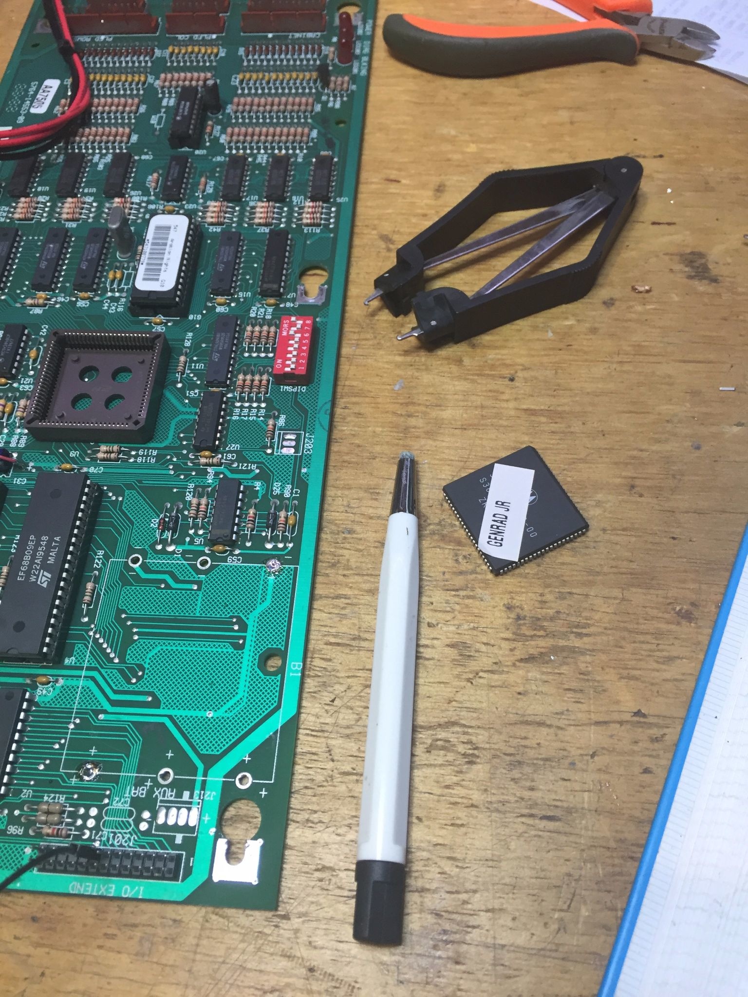
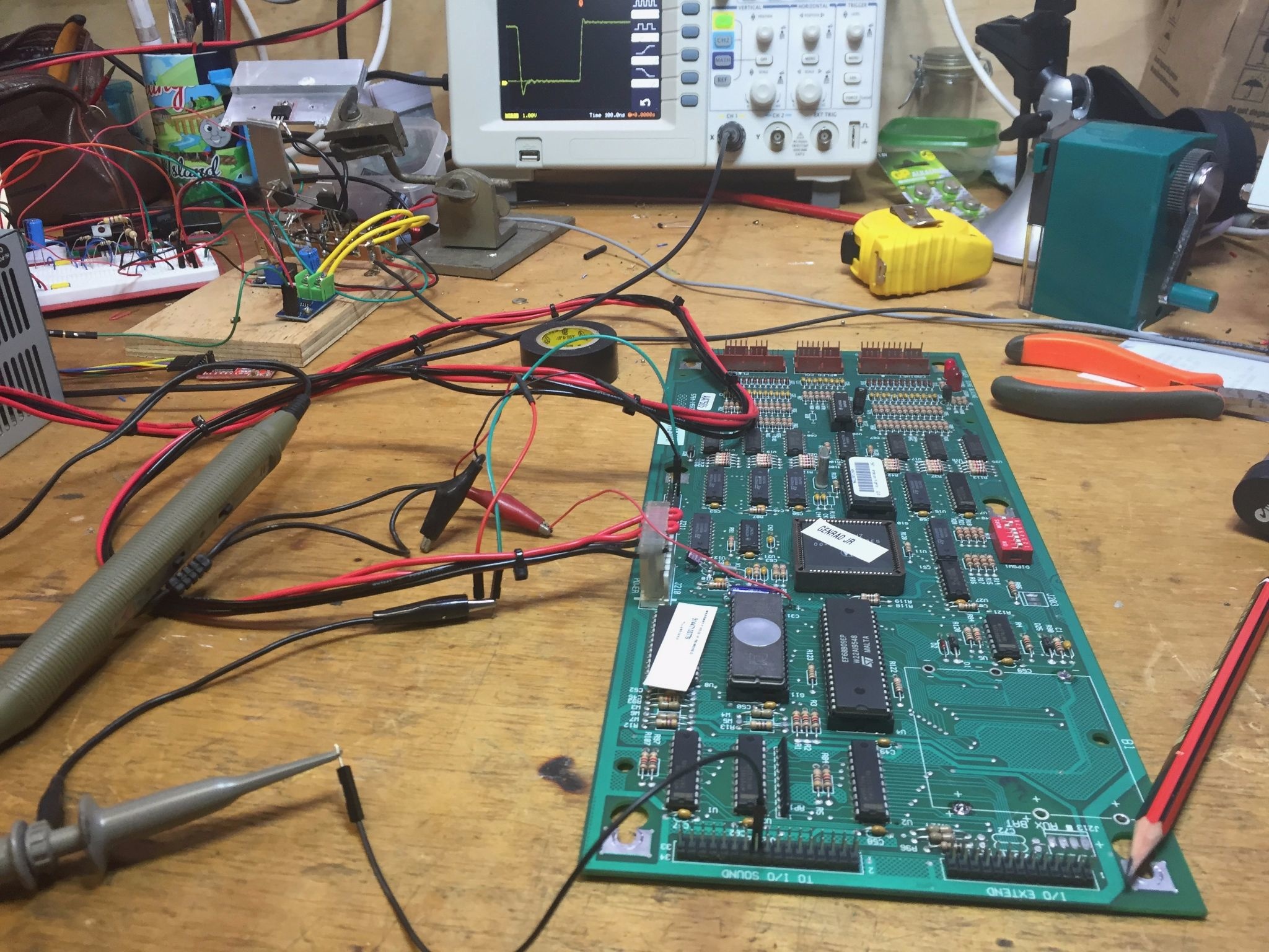
Had an interesting case of a TOTAN that would yo-yo reset. Resetting stopped when the sound board was disconnected. After swapping the CPU board from another machine I knew the fault was on definitely on the CPU board. Suspecting the 3 state transceiver 74LS245 or the buffer 74LS244, I took it to the workshop for a close inspection. Levels measured on the outputs of U1 and U3 looked fine. Moving to the inputs (to see they matched the outputs) I saw on the Oscilloscope the logic level of the WDEN signal was not driving a nice 5 volts … only 2 volts on a logic high! A small amount of pressure on the ASIC socket had the signal return to a full 5 volts.
I removed the ASIC, using a proper puller. The socket showed an exceedingly small amount of corrosion, no corner cracks and no evidence of battery damage. Given how hard it is to desolder these sockets, it was time to use my trusty fibreglass scratch-pen. A quick polish of all the ASIC pins on the socket and the chip was called for. I have a small dental pick I use as well to prod the ASIC pins into a nice curved form. A thorough clean in alcohol and the chip was returned to the socket.
I replaced capacitor C31 while it was on the bench. Easy part to replace and I had a spate of bad ones lately.
The board was returned to its machine and I’m happy to say no further reset problems. I’m not so happy with my scores on the machine, but that is not a problem I can fix on the workbench.
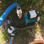
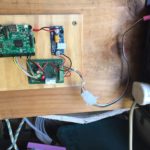
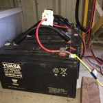
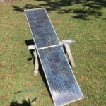
Solar Pi Pump
I’ll post the full details here soon, but I’m pretty happy my Solar powered bore pump is up and running…
Even has status feeds to my phone! (yeah.. OK .. too much… I know)
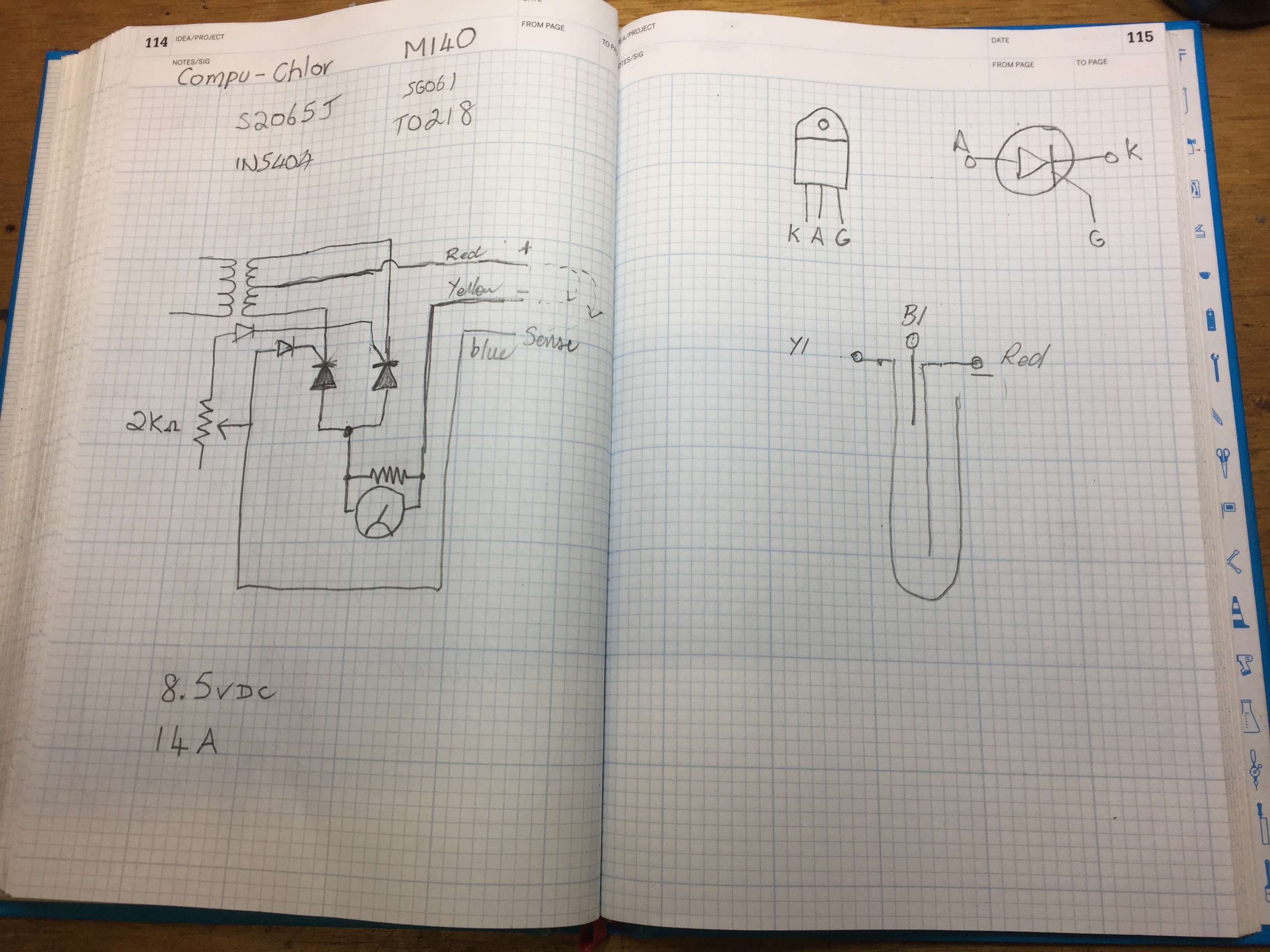
Repair and Document Pool Chlorinator Compu-Chlor M140
Failed Salt Water Chlorinator Cell prompted me to document the circuit in my M140 chlorinator. Pretty simple…
I was able to rig up a test for the power supply using a couple of #44 bulbs and a resistor.
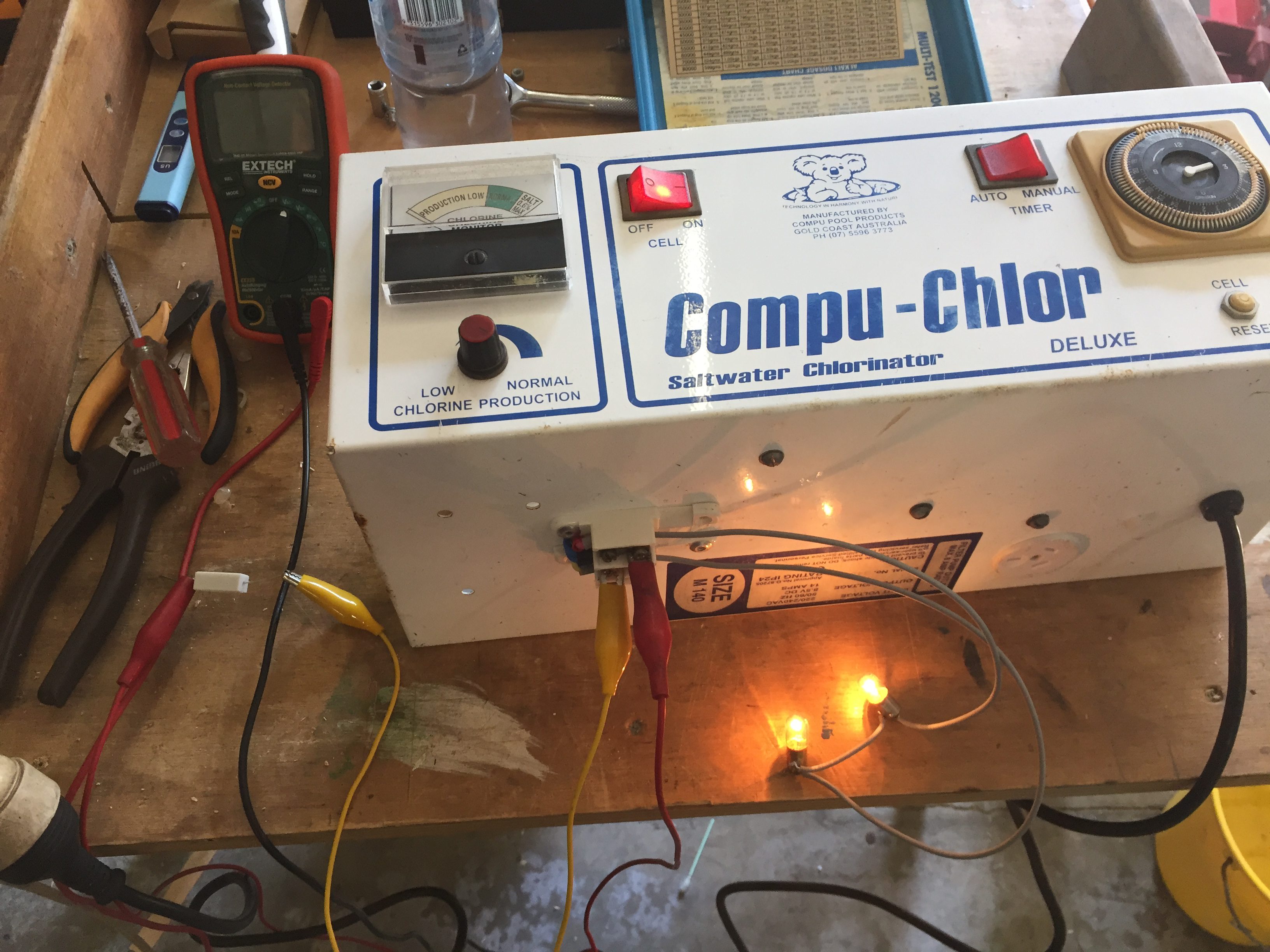
Yup, working fine. Interestingly: the failure mode for the old cell is that it appears to have a “diode” like short between the center plate and the sense pin. I can only speculate that the calcium build up has caused this to act as a “diode”?
SRC is S2065J
Diodes are: 1N5404
This unit can pack out 18AMPS. (Rated at 14A)
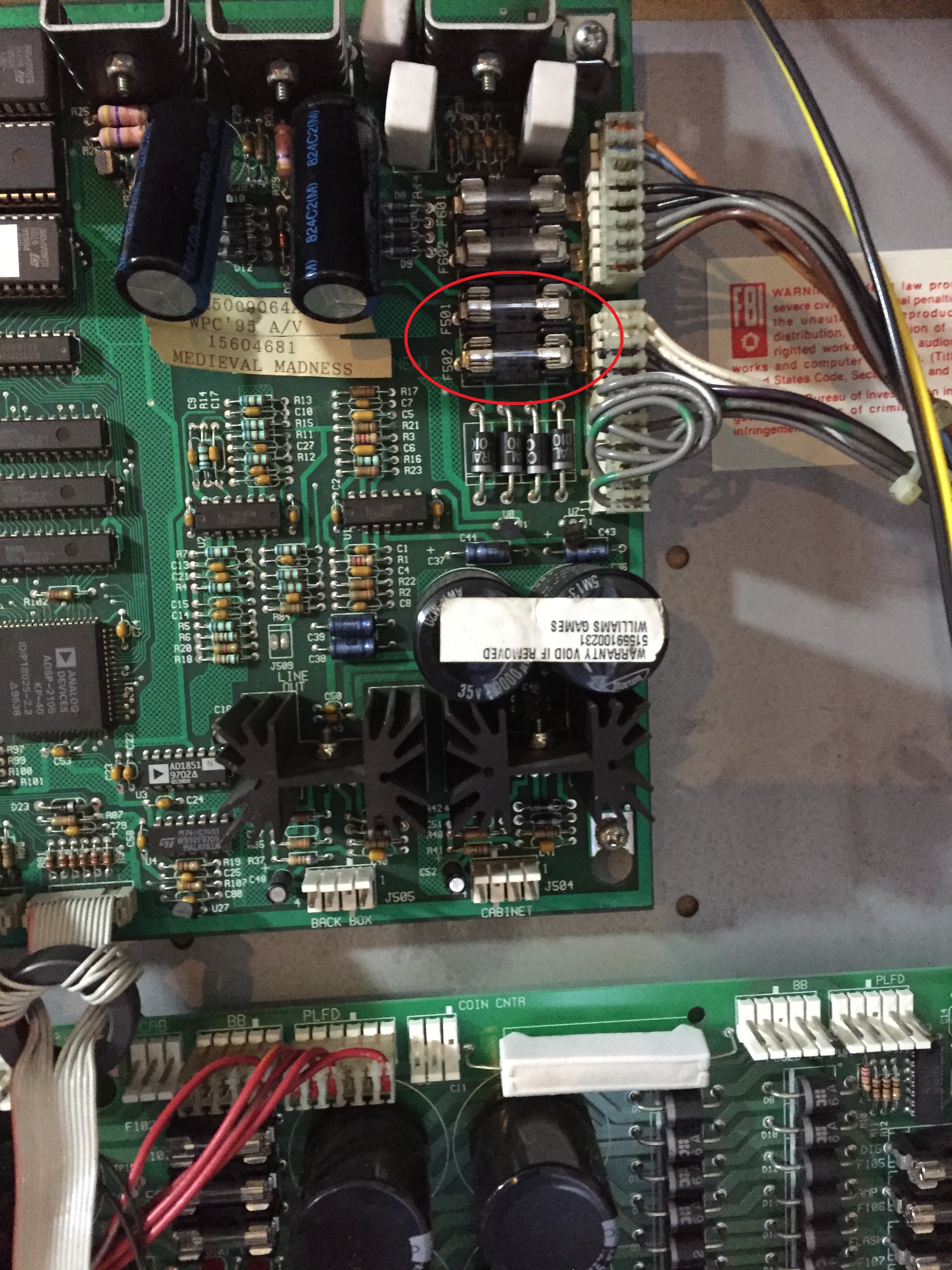
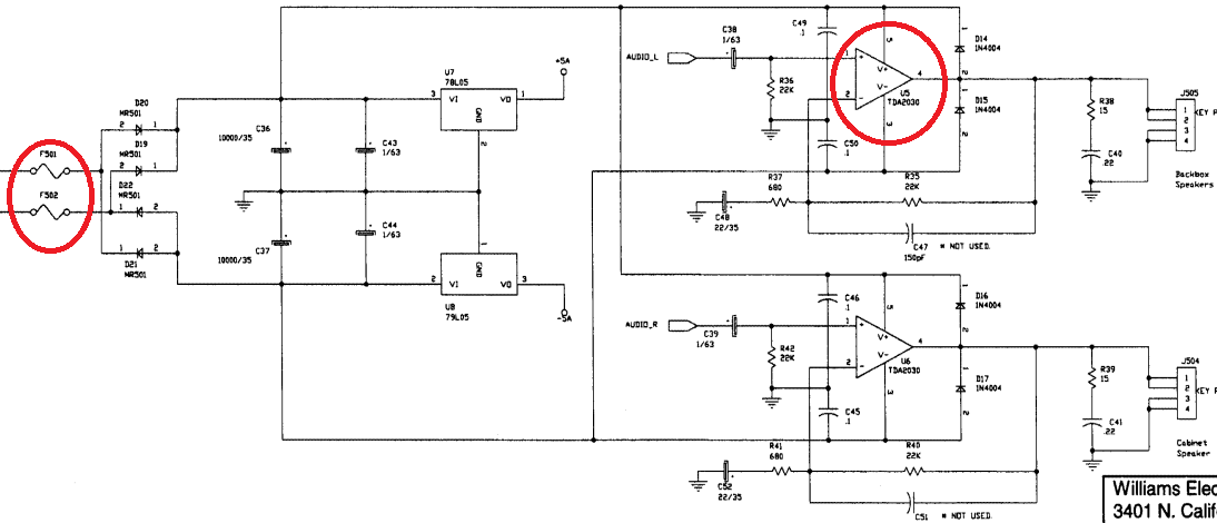
Medieval Madness Pinball – blowing fuses F501 and F502
Working on a MM with fuses blowing on the sound / DMD board.
I returned the board to the workshow, but had trouble replicating the fault. I did not have a dual tracking power-supply to power the audio amplifiers, so I was testing with current limited single supply… no fault.
I finally jury-rigged two power supplies to provide both the positive and negative rails and bingo! We have a short.
The TDA2030 was short circuit between the +ve and -ve rails.
These parts are no longer stocked by the mainstream electronic suppliers, but thankfully are readily available on eBay.
I ordered a new chip, waited the usual 4 weeks for delivery, and this board is now back and operational.
I did a little clean-up of the high-voltage on the DMD driver for this board. Check out the soldering the last repairer left…
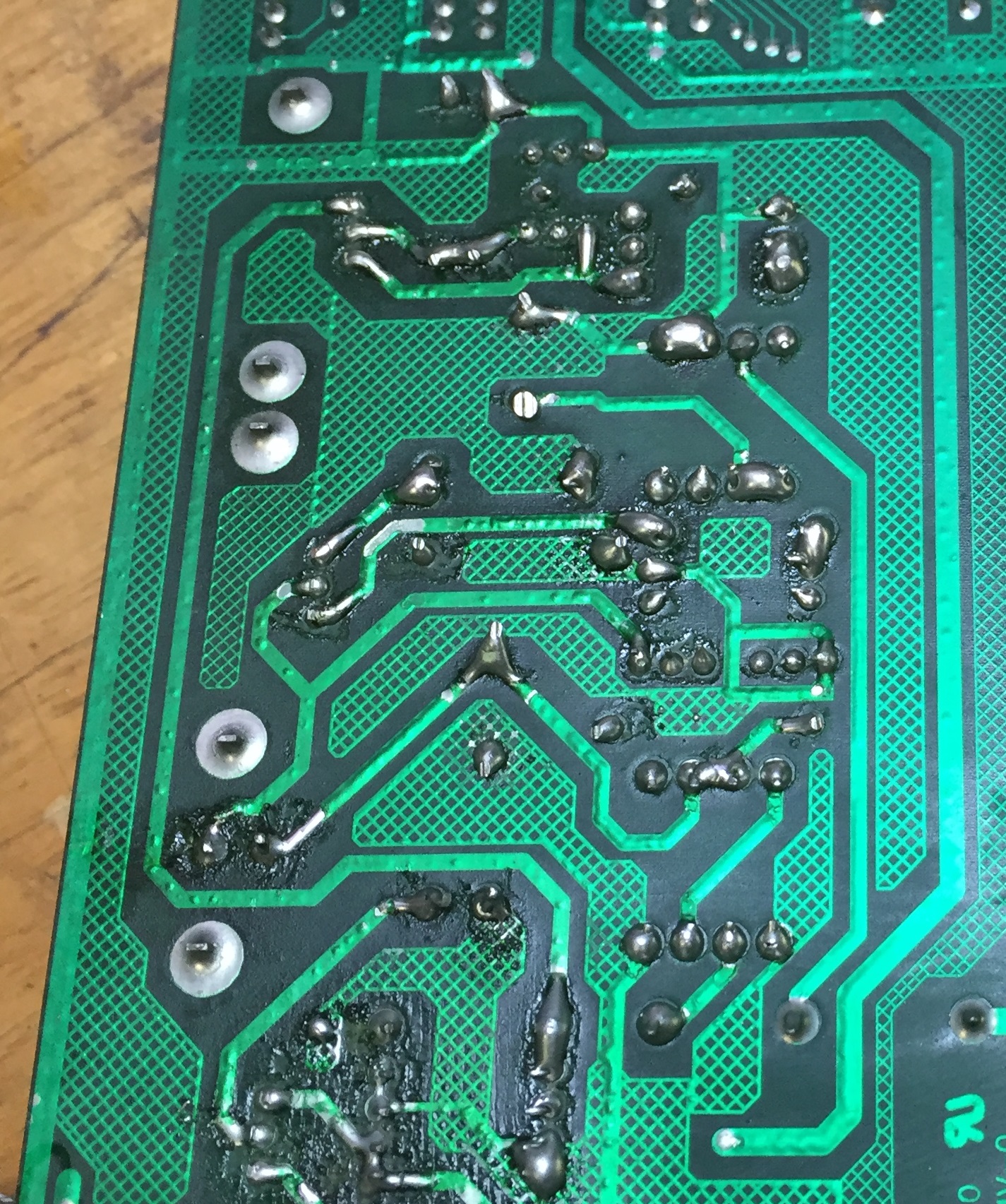
Bloody hell… hats off for actually getting this to work!
Any-how, I felt obliged to clean this up a little without spending too much time on it…